Engine for motorcycle

a technology for motorcycles and engines, applied in the direction of machines/engines, bearing unit rigid support, etc., can solve the problems of difficult shortening the center distance between the crank shaft and the crank shaft, limiting the distance between the main shaft and a shaft other than the main shaft, and reducing the number of parts and assembling steps. , to achieve the effect of shortening the center distan

Inactive Publication Date: 2010-04-13
HONDA MOTOR CO LTD
View PDF15 Cites 3 Cited by
  • Summary
  • Abstract
  • Description
  • Claims
  • Application Information

AI Technical Summary

Benefits of technology

[0008]The present invention has been accomplished in view of the above-mentioned circumstances and it is an object of the invention to provide an engine for a motorcycle able to shorten the center distance between a crank shaft and a main shaft while reducing the number of parts and the number of assembling steps.
[0013]According to the first aspect of the present invention, a second bearing hole is formed in the second support wall. The second bearing hole permits the main shaft to be inserted therein from an opposite end side of the main shaft until one end of the main shaft is fitted and held in the first bearing hole. A second bearing is fitted and held in the second bearing hole so as to be fitted on the main shaft from the opposite side of the main shaft after one end of the main shaft is fitted in the first bearing. Therefore, the second bearing hole can be made smaller in diameter than the through hole heretofore formed, so that it is possible to shorten the center distance between the crank shaft and the main shaft and hence possible to reduce the size of the engine in the longitudinal direction of the motorcycle. In addition, the bearing holder which has heretofore been required becomes unnecessary. Therefore, it becomes possible to decrease the number of parts. Additionally, it is possible to decrease the number of assembling steps because the bearing holder assembly is not needed.
[0014]According to the second aspect of the present invention, it is possible to shorten the distance between the main shaft and the auxiliary devices disposed around the main shaft and hence possible to further reduce the size of the engine.
[0015]According to the third aspect of the present invention, it is possible to disposed an oil pump by utilizing a space created between the crank shaft and the main shaft. In addition, a power transfer mechanism for the transfer of power between the crank shaft or the main shaft and the oil pump can be made compact by disposing it in proximity to the crank shaft or the main shaft which drives the oil pump.
[0016]According to the fourth aspect of the present invention, the counter shaft can be disposed close to the cylinder block in the second bank, whereby the size of the engine can be further reduced in the longitudinal direction of the motorcycle.

Problems solved by technology

In the above structure wherein the main shaft is supported rotatably in the lower case of the crank case at a portion of the lower case other than the surface joined with the upper case, it is difficult to form a bearing by a pair of half portions.
Therefore, a limit is encountered in shortening the distance between the main shaft and a shaft other than the main shaft.
In addition, auxiliary devices which require bearings, such as a shift drum and an oil pump, are disposed in the lower case, so that it is difficult to shorten the center distance between the crank shaft and the main shaft.
In the structure using a bearing holder, the number of parts used increases and the main shaft assembly becomes troublesome.

Method used


Image

  • Engine for motorcycle
  • Engine for motorcycle
  • Engine for motorcycle

Examples


Embodiment Construction

[0034]The present invention will be described hereinunder by way of an embodiment thereof illustrated in the accompanying drawings.

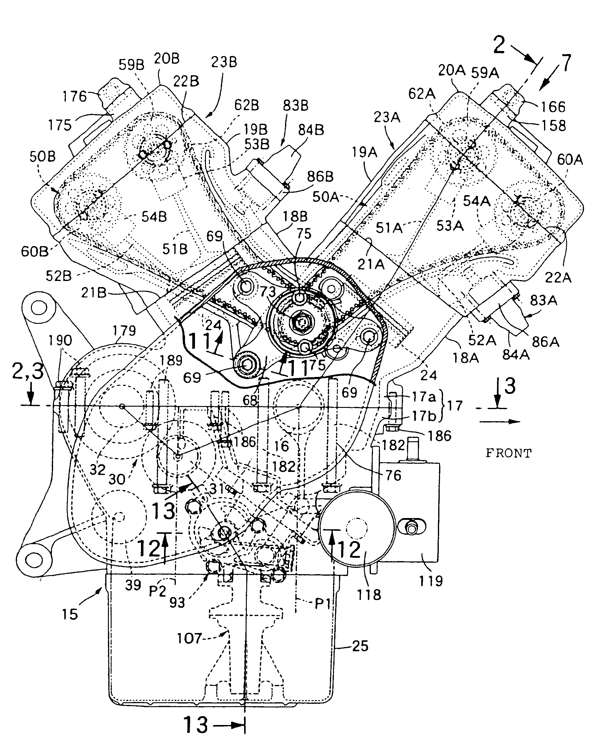
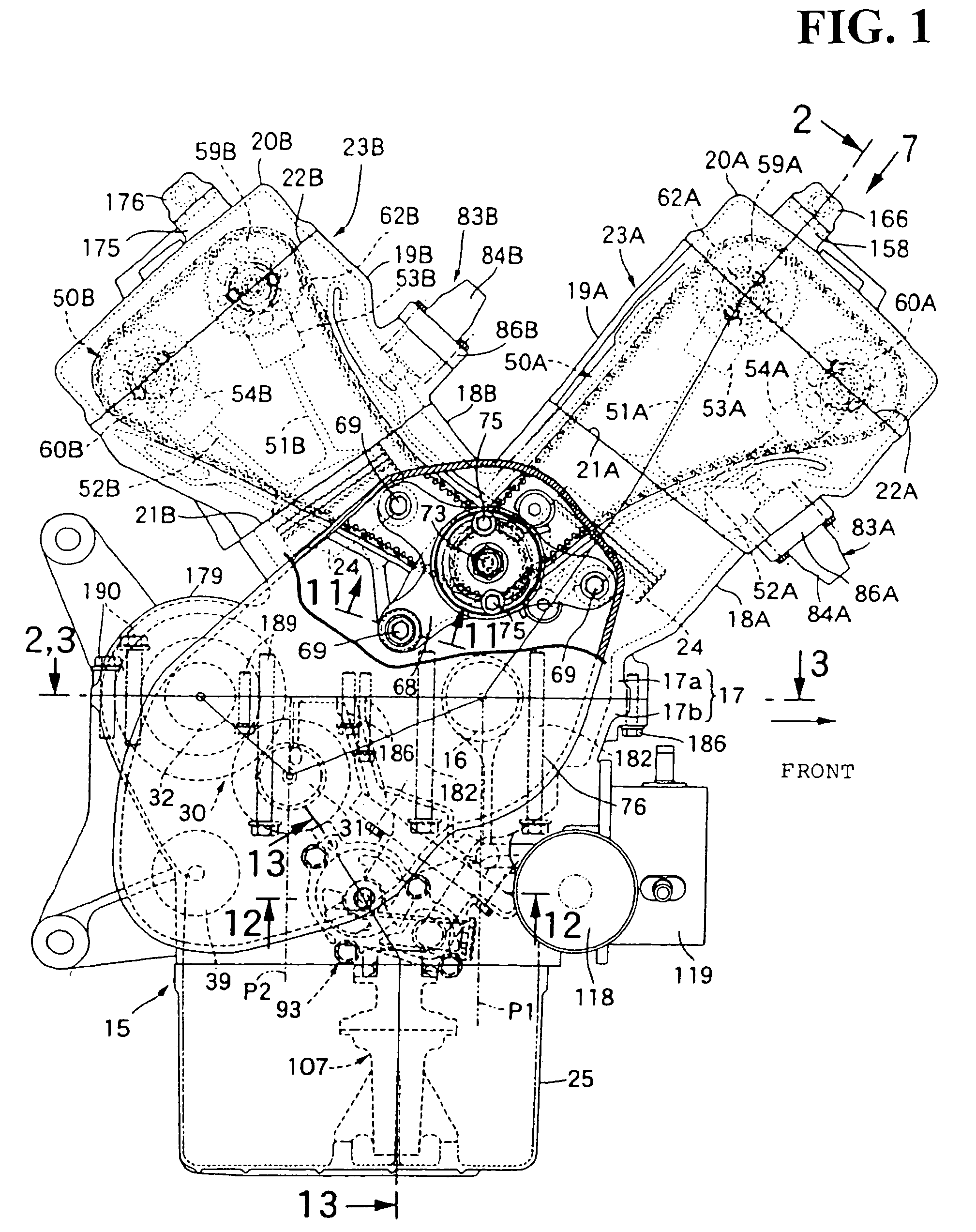
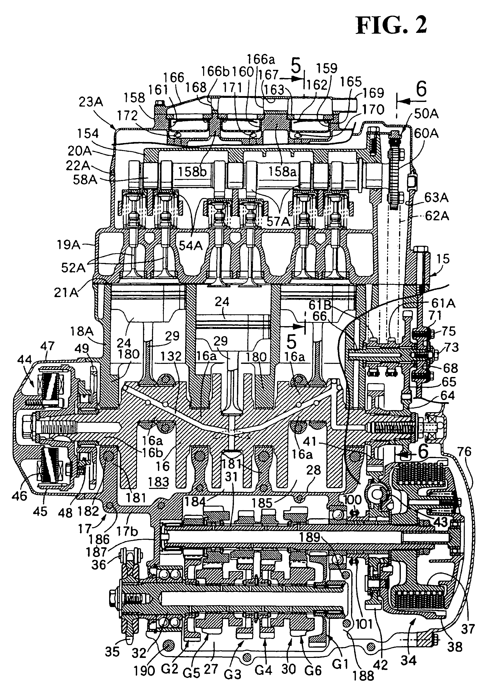
[0035]First, in FIG. 1, for example a five-cylinder V-type engine is mounted on a motorcycle. An engine body 15 of the engine includes a crank case 17 which supports a crank shaft 16 rotatably. The crank shaft 16 has an axis extending in the transverse direction of the motorcycle. A first cylinder block 18A is joined to the crank case 17 on a front side in an advancing direction of the motorcycle. A first cylinder head 19A is joined to an upper-end joining surface 21A of the first cylinder block 18A. A first head cover 20A is joined to an upper-end joining surface 22A of the first cylinder head 19A. A second cylinder block 18B is joined to the crank case 17 on a rear side in the advancing direction of the motorcycle. A second cylinder head 19B is joined to an upper-end joining surface 21B of the second cylinder block 18B. A second head cover 20B is joine...


PUM


Abstract

In an engine for a motorcycle, a main shaft is supported rotatably by first and second support walls of a lower case which constitutes a part of a crank case. The center distance between the crank shaft and the main shaft is to be shortened while attaining a reduction in the number of parts and the number of assembling steps. A first bearing hole is formed in a first support wall for fitting therein and holding a first bearing which is mounted on one end of the main shaft. A second bearing hole is formed in a second support wall which permits the main shaft to be inserted therein from an opposite end side of the main shaft until one end of the main shaft is fitted in the first bearing. A second bearing is fitted and held in the second bearing hole so as to be fitted on the main shaft from the opposite end side of the main shaft after fitting of one end of the main shaft into the first bearing.

Description

CROSS-REFERENCE TO RELATED APPLICATIONS[0001]This nonprovisional application claims priority under 35 U.S.C. § 119(a) on Patent Application No. 2005-009825, filed in Japan on Jan. 18, 2005, the entirety of which is incorporated herein by reference.BACKGROUND OF THE INVENTION[0002]1. Field of the Invention[0003]The present invention relates to an engine for a motorcycle wherein a crank shaft and a counter shaft parallel to the crank shaft are supported rotatably by a crank case. The crank case including an upper case and a lower case joined to each other, and a main shaft having an axis parallel to the crank shaft and the counter shaft is supported rotatably by first and second support walls, the first and second walls being provided in the lower case spaced along the axis of the main shaft.[0004]2. Description of Background Art[0005]For example in Japanese Patent Publication No. Hei 2-43886, there already is known an engine for a motorcycle wherein a crank shaft and a counter shaft ...

Claims


Application Information

Patent Timeline
Patent Type & Authority Patents(United States)
IPC IPC(8): F02B75/32F02B75/22F01M1/02F02B61/02F16C35/067F16H57/021F16H57/023
CPCF01L1/022F01L1/446F01L1/46F02B75/22F01L2103/00F02B61/02F01L2001/0537F01L2303/00
Inventor GUNJI, TORUSUGIURA, HIROYUKI
Owner HONDA MOTOR CO LTD
Why Eureka
Try Eureka