Motorcycle engine and assembling method thereof

a technology for motorcycle engines and assembling methods, which is applied in the direction of gearing details, gearing, transportation and packaging, etc., can solve the problems of reducing the affecting the mounting of transmission output shafts, and inevitably increasing the size of bearing holder closing the transmission output shaft insertion opening, so as to improve the mounting stability and positioning accuracy of bearings. , the effect of improving the mounting rigidity of bearings

Inactive Publication Date: 2009-08-25
SUZUKI MOTOR CORP
View PDF8 Cites 3 Cited by
  • Summary
  • Abstract
  • Description
  • Claims
  • Application Information

AI Technical Summary

Benefits of technology

[0009]The present invention was conceived in consideration of the circumstances mentioned above, and an object of the invention is to provide a motorcycle engine and its assembling method capable of mounting a transmission output shaft effectively along with a transmission driven gear in an engine case through a transmission-output-shaft insertion opening, making compact the engine case by reducing the center distance between the transmission output shaft and a transmission input shaft, improving the positioning accuracy and support rigidity of a bearing of the transmission output shaft, and improving the mountability of the transmission output shaft.
[0030]According to the present invention of the aspects mentioned above, the center distance between the transmission input shaft and the transmission output shaft can be reduced, and the engine case can be made compact. Moreover, the transmission output shaft can be smoothly inserted in the engine case while preventing a transmission driven gear mounted on the transmission output shaft from interfering with a transmission driving gear mounted on the transmission input shaft. The mountability of the transmission output shaft can be enhanced. The transmission output shaft can be reliably positioned by the bearing holder. The eccentric bearing holder can also be easily mounted in the engine case.
[0031]In addition, since the eccentric bearing holder and the bearing holder are cylindrically and tightly fitted in the transmission-output-shaft insertion opening and the circular bearing opening, respectively, fitting portions can be formed by simple cylindrical cutting. This can increase the working accuracy of the fitting portions, and can dramatically increase the positioning accuracy of the bearings. In addition, since the load applied to the bearing of the transmission output shaft can be received by the cylindrical fitting surface in the radial direction of the transmission output shaft, the support rigidity of the bearing can be increased markedly.
[0032]Furthermore, according to the assembling method of the motorcycle engine mentioned above, the transmission output shaft can be easily mounted in the engine case through the transmission-output-shaft insertion opening while preventing the transmission driven gears from interfering with the transmission driving gears.
[0033]In the motorcycle engine according to the present invention, the transmission output shaft deviates from the transmission-output-shaft insertion opening and the eccentric bearing holder toward the transmission input shaft. Therefore, the center distance between the transmission input shaft and the transmission output shaft can be reduced, and the size of the engine case can be reduced thereby. Moreover, the transmission output shaft can be smoothly inserted in the engine case while preventing the transmission driven gears mounted on the transmission output shaft from interfering with the transmission driving gears mounted on the transmission input shaft. Consequently, the mountability of the transmission output shaft can be enhanced.

Problems solved by technology

However, when the size of the transmission-output-shaft insertion opening is set to be larger than that of the transmission driven gear having the largest outer diameter, the bearing holder closing the transmission-output-shaft insertion opening inevitably increases in size, and the bearing of the transmission output shaft fitted in the bearing holder is disposed largely apart from a rim of the transmission-output-shaft insertion opening.
Further, since the bearing of the transmission output shaft is fixed to the lower case section with the bearing holder disposed therebetween, there is a risk that the positioning accuracy of the bearing will decrease depending on the working accuracy of the transmission-output-shaft insertion opening and the bearing holder.
This procedure frequently makes the assembling working difficult.

Method used


Image

  • Motorcycle engine and assembling method thereof
  • Motorcycle engine and assembling method thereof
  • Motorcycle engine and assembling method thereof

Examples


Embodiment Construction

[0050]An embodiment of the present invention will be described hereunder with reference to the accompanying drawings. Further, it is to be noted that terms of “upper”, “lower”, “right”, “left” and the like terms are used herein in the illustration of the drawings or in a general standing state of the a motorcycle.

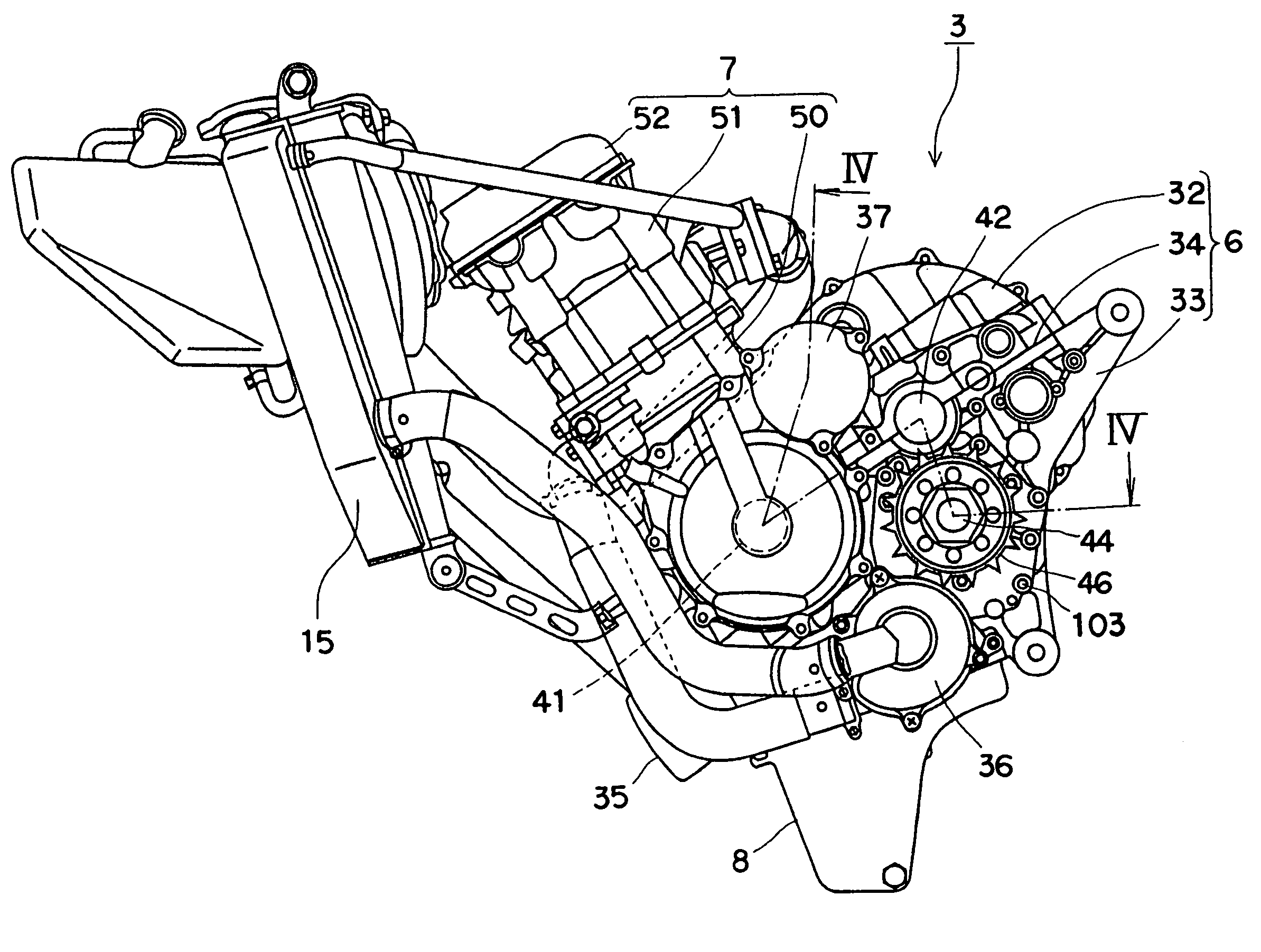
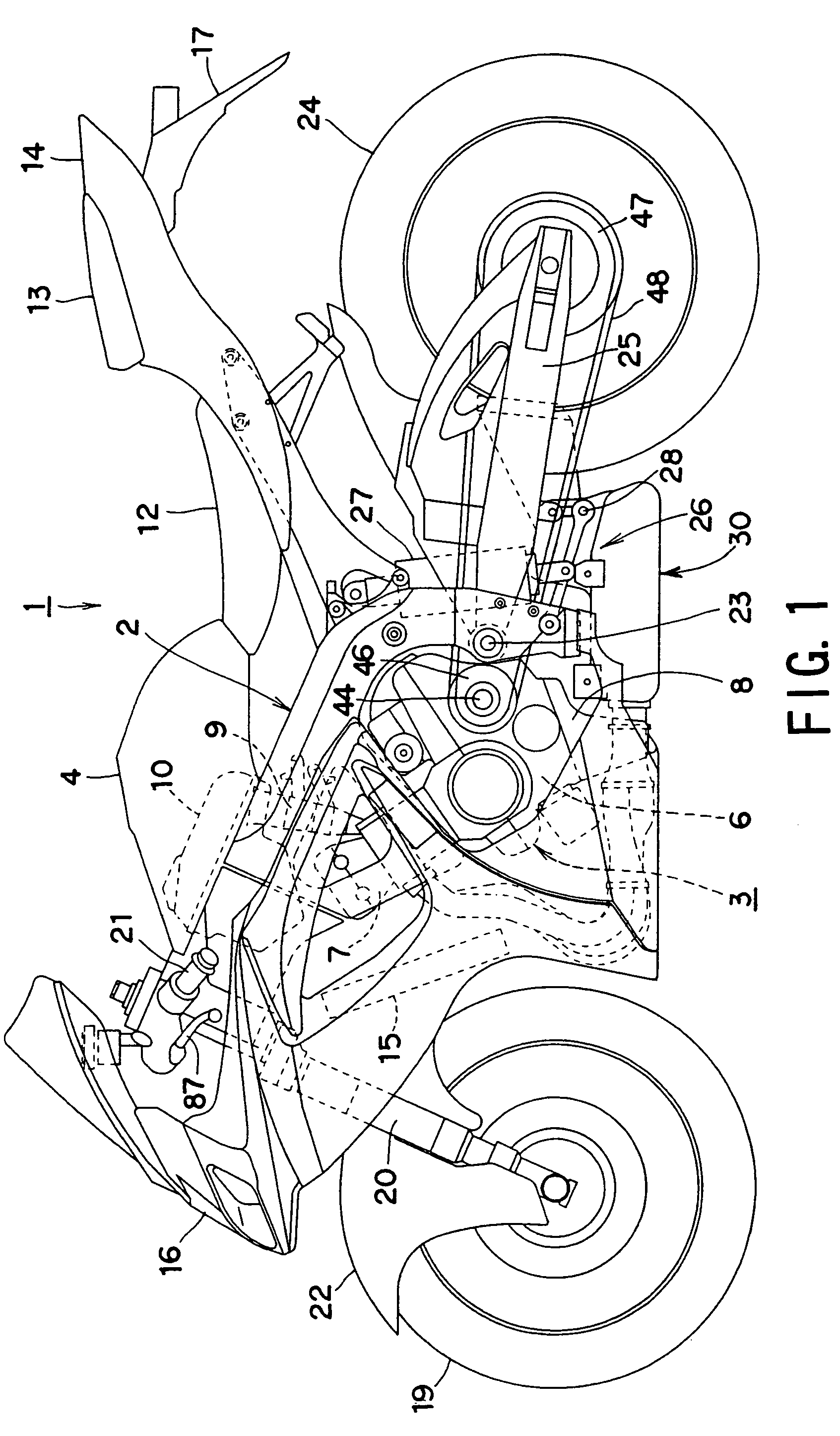
[0051]With reference to FIGS. 1 and 2, a motorcycle 1 includes a body frame 2 made of, for example, aluminum. A water-cooled four-cycle engine 3 including four cylinders arranged in parallel with each other is suspended from the front half portion of the body frame 2, and a fuel tank 4 is mounted on the body frame 2 above the engine 3.

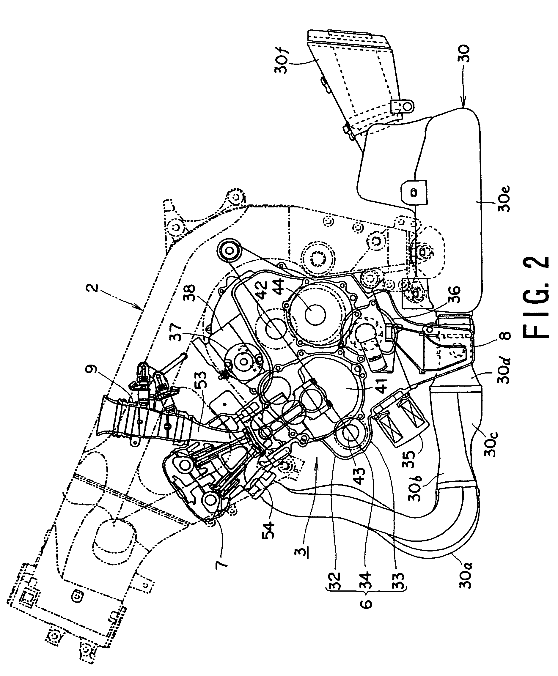
[0052]In the engine 3, a cylinder assembly 7 is disposed on an upper front side of an engine case 6, and an oil pan 8 is disposed on the lower side of the engine case 6. A fuel injector (throttle body) 9 is connected to the rear portion of the cylinder assembly 7, and an air cleaner 10 disposed in a recess formed on the lower surface of the fu...


PUM


Abstract

An engine includes an engine case split into an upper case and a lower case. A crankshaft and a transmission input shaft are rotatably supported at a mating surface between the upper and lower cases, and a transmission output shaft rotated by the transmission input shaft is supported in the lower case. One side face of the lower case has a circular opening through which the transmission output shaft can be inserted from the outside. An eccentric bearing holder holding a bearing that rotatably supports one end of the transmission output shaft is mounted in the opening in a detachable manner from the outside. The axis of the transmission output shaft deviates from the center of the eccentric bearing holder toward the transmission input shaft. The inner diameter of the opening is larger than the outer diameter of the largest one of transmission driven gears of the transmission output shaft.

Description

BACKGROUND OF THE INVENTION[0001]1. Field of the Invention[0002]The present invention relates to a motorcycle engine improving an arrangement of rotation shafts in an engine case and also relates to a method of assembling the engine case.[0003]2. Related Art[0004]Japanese Unexamined Patent Application Publication No. 2004-360773 discloses a motorcycle engine including an engine case split into two sections, namely, an upper case section and a lower case section. In order to reduce the size of the engine case in the front-rear direction, i.e., longitudinal direction of a motorcycle, a crankshaft and a transmission input shaft (counter shaft) extending in the width direction of the motorcycle are rotatably supported at a mating surface between the upper case section and the lower case section, and a transmission output shaft (driving shaft) rotated by the transmission input shaft is supported in the lower case section.[0005]In this layout of the various rotation shafts, the transmissi...

Claims


Application Information

Patent Timeline
Patent Type & Authority Patents(United States)
IPC IPC(8): F16H3/08
CPCF16H3/089F16H2200/0052Y10T74/19223Y10T74/19279Y10T74/2186
Inventor ARAKAWA, HIDETOSHIKATO, KOHEIODA, TOMOYUKI
Owner SUZUKI MOTOR CORP
Why Eureka
Try Eureka