

Range switching apparatus
a range switching and apparatus technology, applied in the direction of gearing details, gearing, transportation and packaging, etc., can solve the problems of increasing the size of the range switching apparatus, increasing the size of the overall range switching mechanism, increasing the distance between the gear shafts, etc., and achieve the effect of suppressing the increase in the size of components
- Summary
- Abstract
- Description
- Claims
- Application Information
AI Technical Summary
Benefits of technology
Problems solved by technology
Method used
Image

Examples
first embodiment
[0031]A first embodiment of the invention is described below with reference to the drawings. Note that, through the drawings, the same or corresponding components are denoted by the same reference numerals.
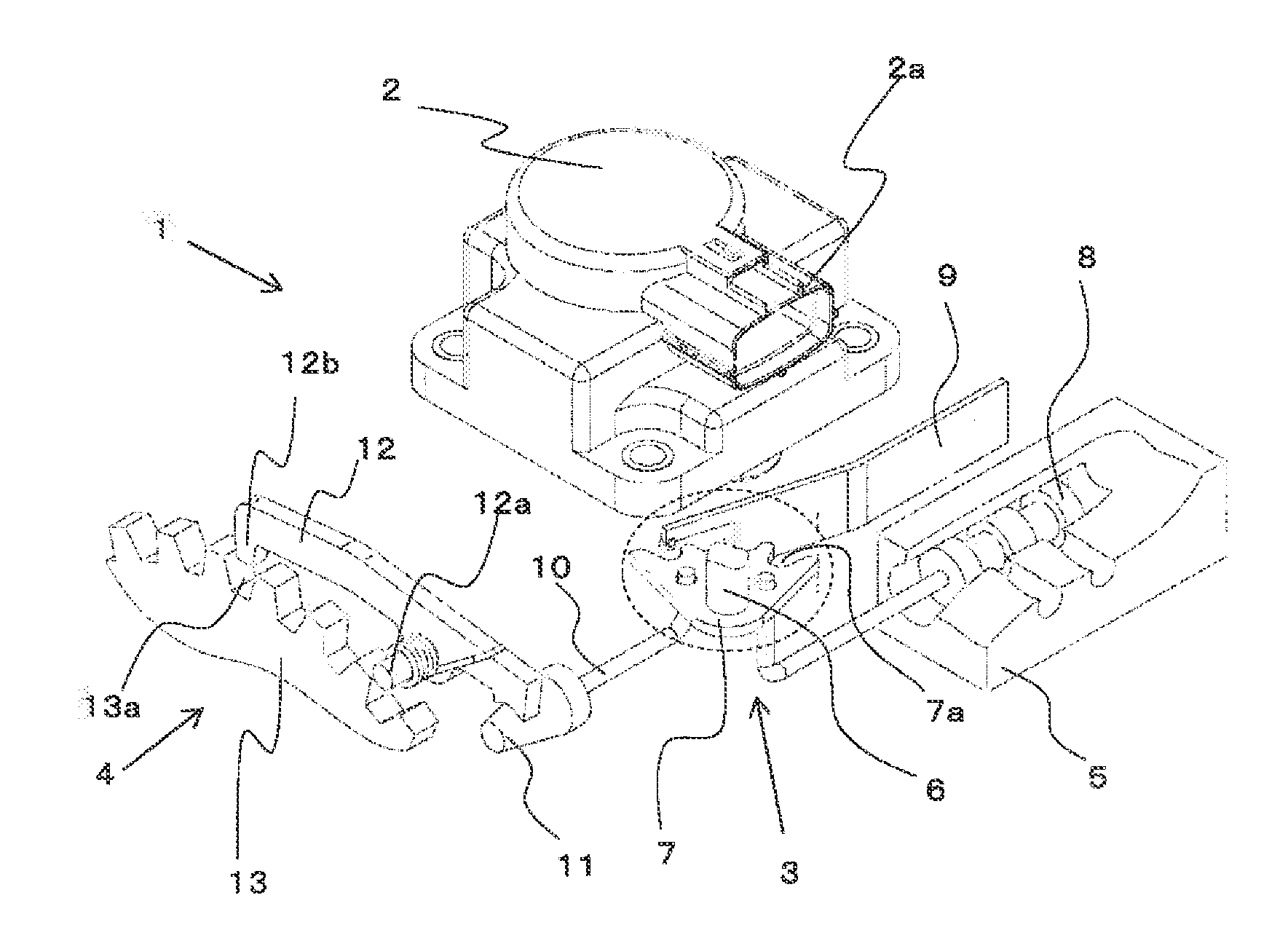
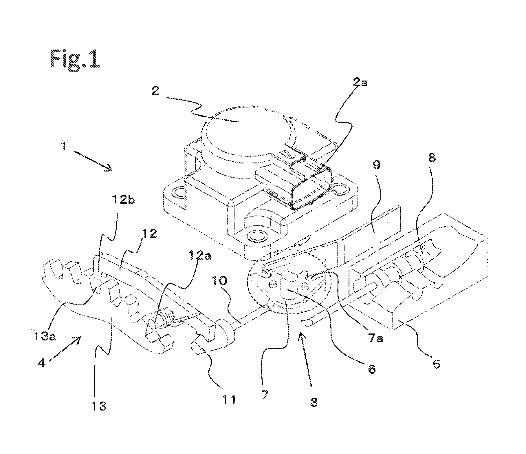
[0032]FIG. 1 is a perspective view schematically showing a range switching apparatus and its peripheral mechanism in accordance with the first embodiment of the invention. As shown in FIG. 1, a range switching mechanism 1 includes a range switching apparatus 2 that is a main part of the first embodiment of the invention, a detent mechanism 3, a parking mechanism 4, and a valve body 5.
[0033]Here, the range switching apparatus 2 is configured so as to be, for example, mounted on an automatic transmission installed in a vehicle, and includes a connector 2a through which a shift signal (electric signal) from a shift lever (range selecting means) used by a driver to select a shift range is supplied. Based on this shift signal, the range switching apparatus 2 rotationally drives a shift...
second embodiment
[0053]FIG. 6 is a schematic plan view showing the configuration of a gear speed reduction mechanism of a range switching apparatus in accordance with a second embodiment of the invention.
[0054]In FIG. 6, in the range switching apparatus 2, a detent spring 49 having a roller 48 at the tip is provided, and the gear wheel 28 having the internal gear 28b in the inner periphery arc portion has concave and convex portions 28c corresponding to the shift ranges formed in the outer periphery arc portion, and then, the roller 48 of the detent spring 49 is configured to engage the concave and convex portions 28c of the gear wheel 28.
[0055]In the range switching apparatus 2 of the second embodiment configured as above, the detent spring 49 is configured in the range switching apparatus 2, which eliminates the need for configuring the detent plate 7 and the detent spring 9 in the transmission, allowing the configuration of the transmission to be simplified.
[0056]Further, in the range switching a...
third embodiment
[0057]FIG. 7 is a schematic plan view showing the configuration of a gear speed reduction mechanism of a range switching apparatus in accordance with a third embodiment of the invention. FIG. 8 is a main part cross-sectional view showing the cross section along the line C-C in FIG. 7. Unlike the first and second embodiments, in the third embodiment, the gear wheel 28 does not have internal teeth, but has external teeth.
[0058]In FIG. 7, the gear wheel 28 has a sector shape and includes one or more contact members 50 having a spring property on one side flat surface 28d with an insulating member 51 between the contact members 50 and the gear wheel 28. Further, in addition to this, a plurality of arc-shaped stationary terminals 52 are placed on the rear body 36 at positions opposite to the contact members 50, then the switching function in response to the switched range position is provided by making these members in contact with (electrically connected to) or not in contact with (elec...
PUM
 Abstract
Description
Claims
Application Information