Leakage checking up device for evaporation fuel purifying system

A technology for purifying system and evaporating fuel, applied in charging system, measuring device, condensed fuel collection/return, etc., can solve problems such as damage to leak detection accuracy

Active Publication Date: 2004-09-08
DENSO CORP
View PDF4 Cites 37 Cited by
  • Summary
  • Abstract
  • Description
  • Claims
  • Application Information

AI Technical Summary

Problems solved by technology

Even if the leak hole and the reference port have the same diameter, such as φ0.5mm, it will cause a deviation between the reference pressure and the saturation pressure, which damages the accuracy of leak detection

Method used


Image

  • Leakage checking up device for evaporation fuel purifying system
  • Leakage checking up device for evaporation fuel purifying system
  • Leakage checking up device for evaporation fuel purifying system

Examples


Embodiment Construction

[0035] (first embodiment)

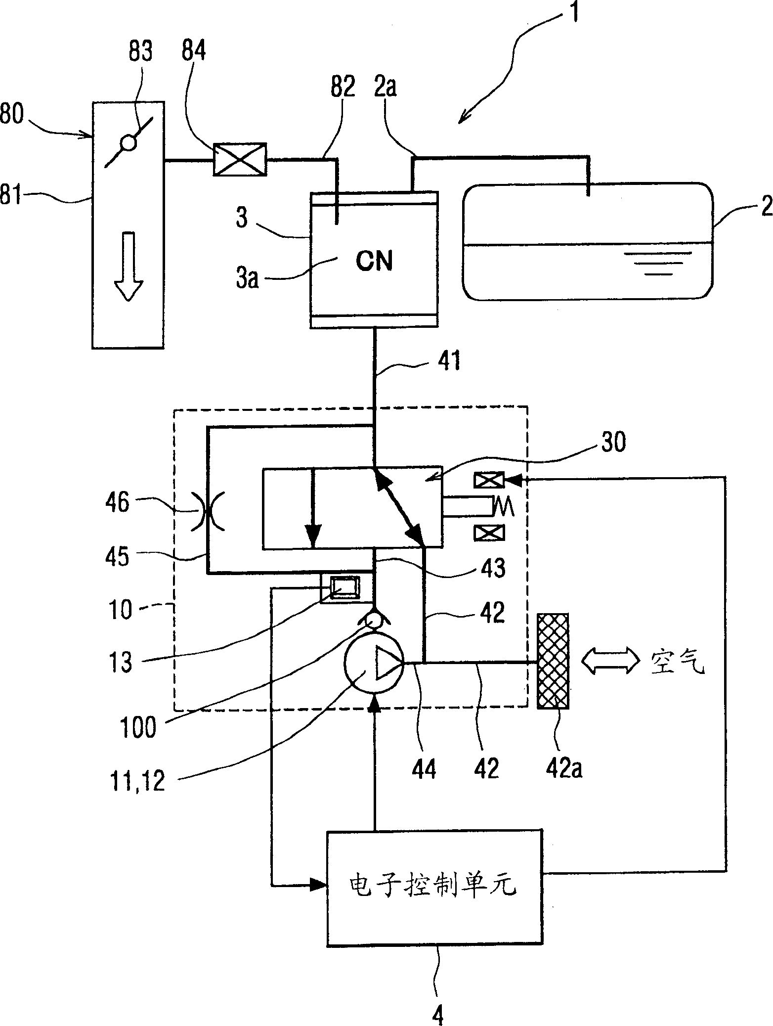
[0036] Such as figure 1 As shown, the evaporative fuel purification system includes a fuel tank 2, a canister 3 as an absorption filter connected to the fuel tank 2 through a connecting fluid passage 2a and having a ventilation fluid passage 41, and a purge control valve 84 as a ventilation valve. One end of the ventilation valve 84 is connected to the canister 3 through the valve fluid passage 82 , and the other end of the ventilation valve 84 is connected to the intake system 80 of the internal combustion engine through the valve fluid passage 82 . The canister 3 contains an adsorbent 3a such as activated carbon.

[0037] A part of the fuel held in the fuel tank 2 evaporates, and the evaporated fuel is generated in the fuel tank 2 . This evaporated fuel is guided into the canister 3, where it is temporarily absorbed and accumulated. When purge control valve 84 is opened by air due to the reduced pressure in suction system 80 , air is drawn thr...


PUM


Abstract

An evaporated fuel purge system has a fuel tank, an adsorption filter and a purge control valve. The evaporated fuel purge system is pressurized and depressurized through a venting flow path by a pump, so that the state of leakage therefrom is thereby inspected. For this inspection, a motor unit for driving the pump which applies or reduces pressure, an in-vehicle battery and a voltage control circuit which controls a battery voltage to a predetermined voltage and supplies the motor unit with a current are provided. The voltage control circuit is located in a pump chamber which forms a part of air outlet passage.

Description

technical field [0001] The invention relates to a leak detection device for an evaporative fuel purification system. Background technique [0002] A device for purifying vaporized fuel includes, for example, a fuel tank of an internal combustion engine, a canister, and a purge control valve. The evaporated fuel purification system is designed such that evaporated fuel generated in the fuel tank is temporarily absorbed into the canister. The evaporated fuel absorbed into the canister is absorbed into the air intake system of the internal combustion engine through the purge control valve together with the fresh air introduced through the fresh air inlet in the canister. However, when there is a crack or the like in the conduit or container constituting the recovery passage of evaporated fuel extending from the fuel tank through the canister to the purge control valve, the evaporated fuel leaks to the outside, and release of the evaporated fuel cannot be sufficiently achieved....

Claims


Application Information

Patent Timeline
Patent Type & Authority Applications(China)
IPC IPC(8): B60K15/035F02D45/00F02M25/08F02M33/02G01M3/04G01M3/08G01M3/26G01M99/00
CPCF02M25/0818
Inventor 小林充幸加纳政雄稻垣幸一
Owner DENSO CORP
Why Eureka
Try Eureka