Optical Unit and Endoscope

an endoscope and optical technology, applied in the field of optical units and endoscopes, can solve problems such as difficult observation of object images

Active Publication Date: 2013-06-20
OLYMPUS CORP
View PDF0 Cites 15 Cited by
  • Summary
  • Abstract
  • Description
  • Claims
  • Application Information

AI Technical Summary

Problems solved by technology

When therapy using laser light with an infrared wavelength is performed, light reflected from a site subjected to the therapy is very intense and thus cannot sufficiently be cut off by an infrared light cut-off filter, and a resulting observation screen is extremely bright, which may make observation of an object image difficult.

Method used


Image

  • Optical Unit and Endoscope
  • Optical Unit and Endoscope
  • Optical Unit and Endoscope

Examples


first embodiment

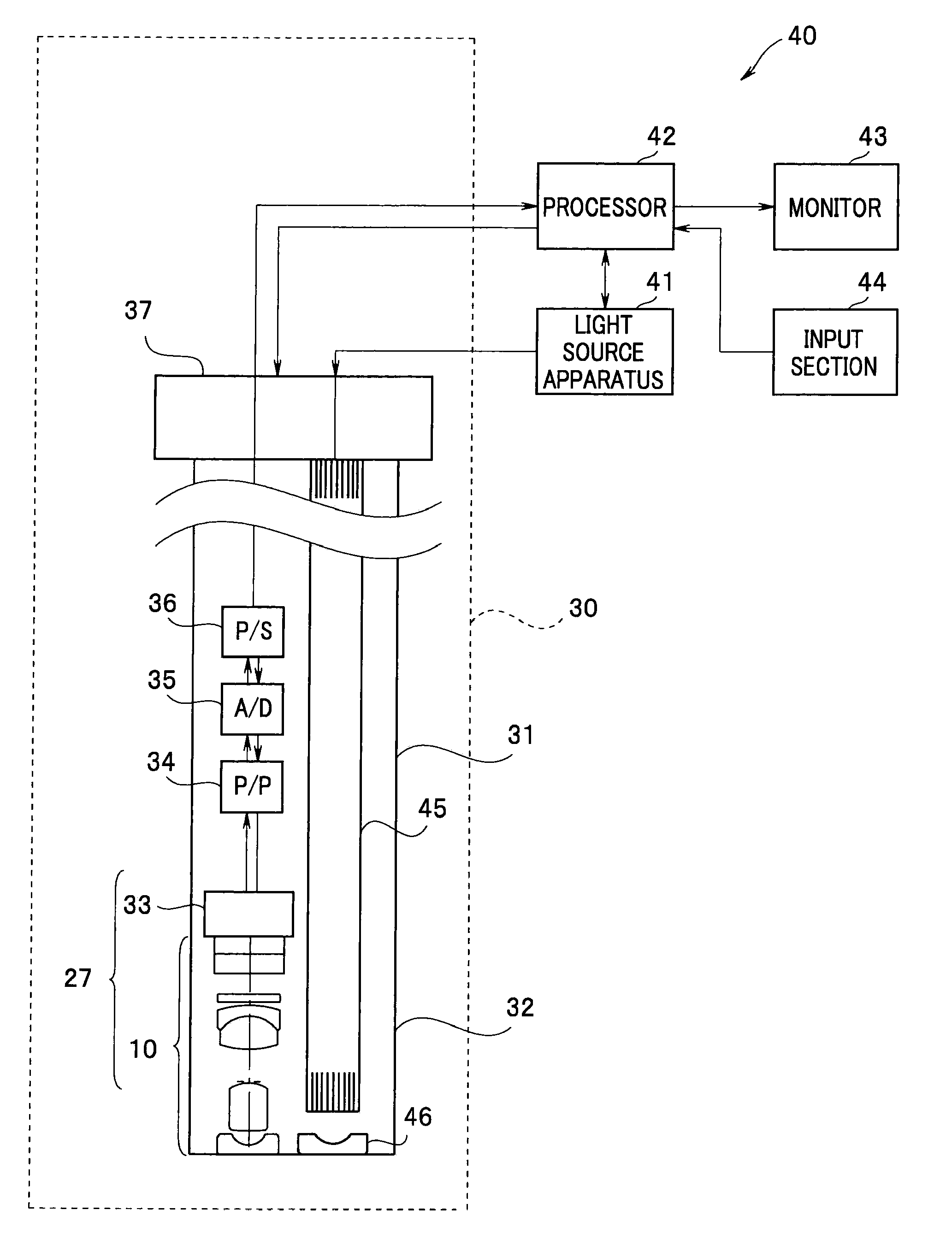
[0020]First, an optical unit 10 according to a first embodiment and an endoscope 30 including the optical unit 10 will be described. As illustrated in FIG. 1, the endoscope 30 forms an endoscope system 40 jointly with a light source apparatus 41 and a processor 42. The endoscope 30 includes an insertion portion 31 to be inserted into the body of a subject. The light source apparatus 41 generates illuminating light that illuminates the inside of the body. The processor 42 performs various types of signal processing and performs control of the endoscope system 40.

[0021]Inside the insertion portion 31 of the endoscope 30, light guide fibers 45 that guide illuminating light from the light source apparatus 41 to a distal end portion 32 is inserted to illuminate the inside of the body via an illumination optical system 46. Note that FIG. 1 illustrates only an object-side lens in the illumination optical system 46.

[0022]The processor 42 can be used as an endoscope system suitable for a pur...

second embodiment

[0042]As illustrated in FIGS. 6 and 7, an optical unit 10A in an endoscope 30A according to a second embodiment includes a front lens group FL (a plano-concave first negative lens L1, a second positive lens L2 that is convex toward the image plane side and a third positive lens L3 that is convex toward the object side), an aperture diaphragm BI, a rear lens group RL (a biconvex fourth positive lens L4, a biconvex fifth positive lens L5 and a sixth negative lens L6 that is convex toward the image plane side), an infrared absorption filter F1, a filter F2, a cover glass G1 and a CCD cover glass G2 in this order from the object side. The fifth positive lens L5 and the sixth negative lens L6 are joined together and the cover glass G1 and the CCD cover glass G2 are joined together, respectively. Furthermore, reference numerals FI1 to FI4 denote flare diaphragms.

[0043]On the object side of the filter F2, an LD laser light cut-off film FA is formed while on the image plane side of the filt...

third embodiment

[0046]As illustrated in FIGS. 8 and 9, an optical unit 10B in an endoscope 30B according to a third embodiment includes a front lens group FL (a plano-concave first negative lens L1), an infrared absorption filter F1 and a second positive lens L2 that is convex toward the object side, an aperture diaphragm BI, a rear lens group RL (a biconvex third positive lens L3, a biconvex fourth positive lens L4 and a fifth negative lens L5 that is convex toward the image plane side), a filter F2, a cover glass G1 and a CCD cover glass G2 in this order from the object side. The fourth positive lens L4 and the fifth negative lens L5 are joined together and the cover glass G1 and the CCD cover glass G2 are joined together, respectively. Also, reference numerals FI1 to FI5 are flare diaphragms.

[0047]On the object side of the filter F2 that is a transparent parallel plate, an LD laser light cut-off film FA is formed while on the image plane side of the filter F2, a YAG laser light cut-off film FB i...


PUM


Abstract

An optical unit includes: a plurality of lenses that form an object image on an image plane that is a light-receiving surface of a CCD; an aperture diaphragm; and an infrared absorption filter disposed on the image plane side relative to the aperture diaphragm, the infrared absorption filter including coating surfaces resulting from a YAG laser cut-off film and an LD laser cut-off film that each cut off predetermined laser light being formed respectively, and an F number FNO, a maximum image height IH, and a distance Δd between a paraxial image formation position in a ghost optical path on which a light beam emitted from the aperture diaphragm BI is reflected by the image plane and further reflected by the coating surface and reaches the image plane again and the image plane satisfy (Expression 1):0.75<|FNO·IH / Δd|<2.0   (Expression 1).

Description

CROSS REFERENCE TO RELATED APPLICATION[0001]This application is a continuation application of PCT / JP2012 / 063433 filed on May 25, 2012 and claims benefit of Japanese Application No. 2011-126547 filed in Japan on Jun. 6, 2011, the entire contents of which are incorporated herein by this reference.BACKGROUND OF THE INVENTION[0002]1. Field of the Invention[0003]The present invention relates to an optical unit and an endoscope including the optical unit.[0004]2. Description of the Related Art[0005]Endoscopes are used for observation of an inside of a subject that cannot be observed from an outside. In the case of electronic endoscopes, in a distal end portion of an insertion portion, which is to be inserted into a body cavity, a CCD (charge coupled device) is incorporated together with an optical unit (image-formation optical system). Because a CCD has a relatively high sensitivity to infrared light, an optical unit including an infrared light cut-off filter is used for proper color repr...

Claims


Application Information

Patent Timeline
Patent Type & Authority Applications(United States)
IPC IPC(8): H04N5/335H04N7/18
CPCG02B23/243G02B27/0018A61B5/0031G02B5/208H04N5/335A61B1/051A61B1/00006A61B1/00096A61B1/00186A61B1/00188H04N7/18H04N25/00
Inventor KAMO, YUJI
Owner OLYMPUS CORP
Why Eureka
Try Eureka