Micro-strip line absorption band-pass filter

A band-pass filter and absorbing technology, applied in the field of filters, can solve the problems of difficult realization of discrete components of filters, loss of circuit performance, poor compatibility, etc., and achieve compact structure, high working frequency band, and good compatibility Effect

Inactive Publication Date: 2014-07-16
UNIV OF ELECTRONICS SCI & TECH OF CHINA
View PDF2 Cites 15 Cited by
  • Summary
  • Abstract
  • Description
  • Claims
  • Application Information

AI Technical Summary

Problems solved by technology

[0004] As far as the operating frequency is concerned, when the operating frequency exceeds 500MHz, the filter is difficult to implement using discrete components. This is because the operating wavelength is close to the physical size of the filter components, which causes various losses and seriously deteriorates the circuit performance.
And the traditional LC absorption filter is not easy to integrate with active devices, and the compatibility is not good

Method used


Image

  • Micro-strip line absorption band-pass filter
  • Micro-strip line absorption band-pass filter
  • Micro-strip line absorption band-pass filter

Examples


Embodiment 1

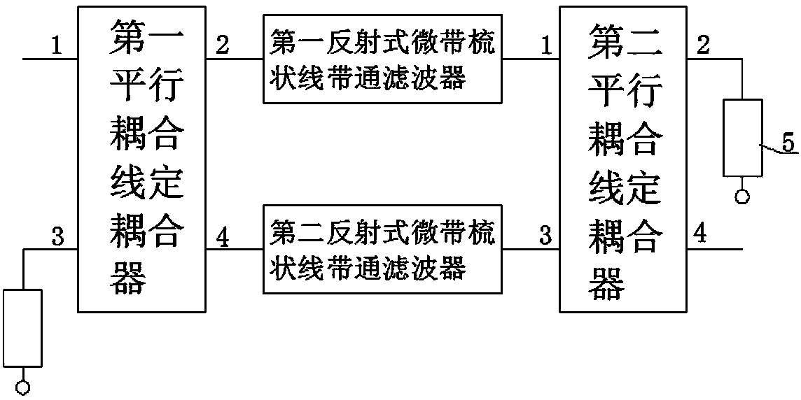
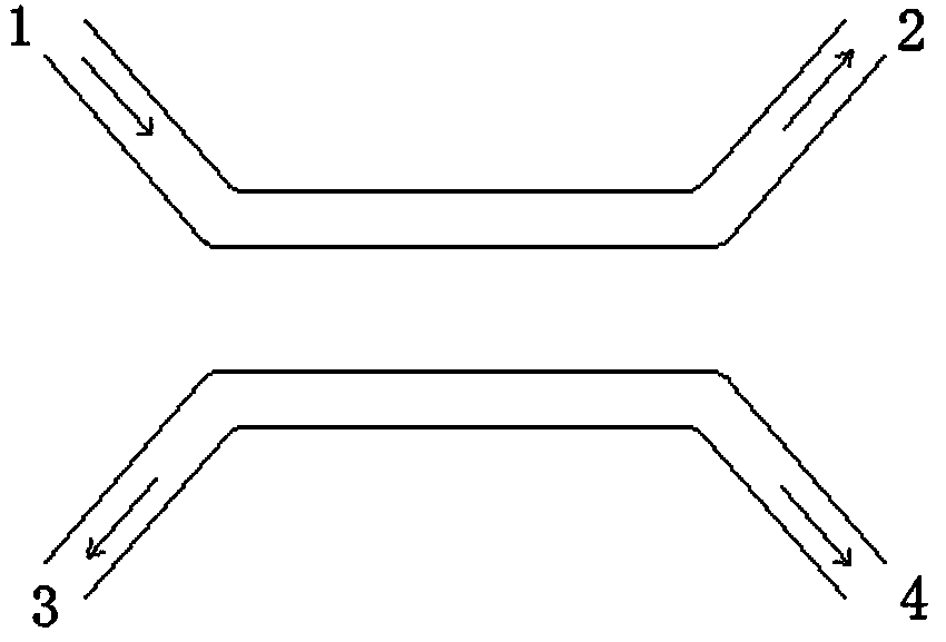
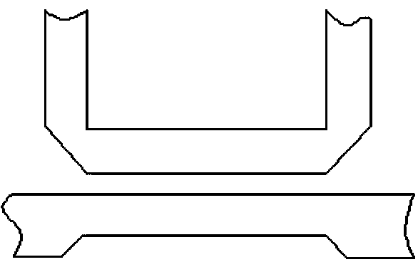
[0032] The parallel coupled line directional coupler of this embodiment selects the parallel coupled line 3dB directional coupler, and the parallel coupled line coupler and the reflective microstrip comb line bandpass filter are all composed of microstrip lines. The two parallel coupled line directional couplers are the same, and the structure diagram of the parallel coupled line 3dB directional coupler is as follows: figure 2 As shown, the circuit layout is shown as image 3 shown. The first and second reflective microstrip comb-line bandpass filters are the same, and the structural diagram of the reflective microstrip comb-line bandpass filter is as follows Figure 4 As shown, the circuit layout is shown as Figure 5 As shown, the structure diagram of the microstrip absorption bandpass filter composed of this embodiment is as follows figure 1 As shown, the circuit layout is shown as Image 6 shown.


PUM


Abstract

The invention discloses a micro-strip line absorption band-pass filter. The micro-strip line absorption band-pass filter is used for solving the problems that an existing LC absorption filter is not prone to being integrated with an active device and poor in compatibility. The micro-strip line absorption band-pass filter comprises two identical parallel coupled line directional couplers, two identical micro-strip pectinate line band-pass filters and a matched load. The micro-strip line absorption band-pass filter has the advantages of being compact in structure, high in working frequency band, wide in bandwidth, low in cost, prone to being integrated with the active device, good in compatibility and simple to design.

Description

technical field [0001] The invention belongs to the technical field of filters, and in particular relates to a microstrip line absorption bandpass filter. Background technique [0002] From communication systems to radio astronomy, filters are essential microwave components. Almost all microwave receivers, transmitters and microwave test equipment require the function of filters. The commonly used filter is a reflective filter, which achieves the purpose of suppressing filtering by reflecting the energy of unwanted frequency components back to the signal source, and realizes the frequency selection function. However, some occasions require the use of absorption filters to absorb out-of-band energy. For example, it is used in high-power transmitters to protect high-power tubes from harmful resonance caused by reflected energy. High-gain amplifiers are absolutely stable in the test environment, but out-of-band signals in the packaging environment will cause unnecessary feedb...

Claims


Application Information

Patent Timeline
Patent Type & Authority Applications(China)
IPC IPC(8): H01P1/203
Inventor 秦巍巍石玉钟慧赵宝林
Owner UNIV OF ELECTRONICS SCI & TECH OF CHINA
Why Eureka
Try Eureka