Carriage structure of car body

A frame structure and vehicle body technology, applied in the structural field of the connecting part, can solve the problem of not being able to improve the corner strength of the connecting support beam and the upper side beam, and achieve the effects of easy installation, simplified shape, and reduced manufacturing cost

Inactive Publication Date: 2004-09-22
MITSUBISHI MOTORS CORP +1
View PDF1 Cites 10 Cited by
  • Summary
  • Abstract
  • Description
  • Claims
  • Application Information

AI Technical Summary

Problems solved by technology

However, no matter what kind of reinforcing member is provided in the straight portion of t

Method used


Image

  • Carriage structure of car body
  • Carriage structure of car body
  • Carriage structure of car body

Examples


Embodiment Construction

[0015] Next, the embodiments of the present invention will be described, and the same parts as those of the above-mentioned conventional device and the same parts of the respective embodiments will be given the same reference numerals, respectively. However, the present invention is not limited to the examples described below, and various changes can be made without departing from the gist of the present invention.

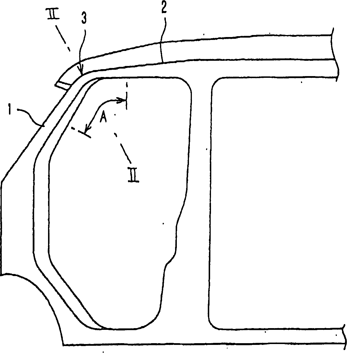
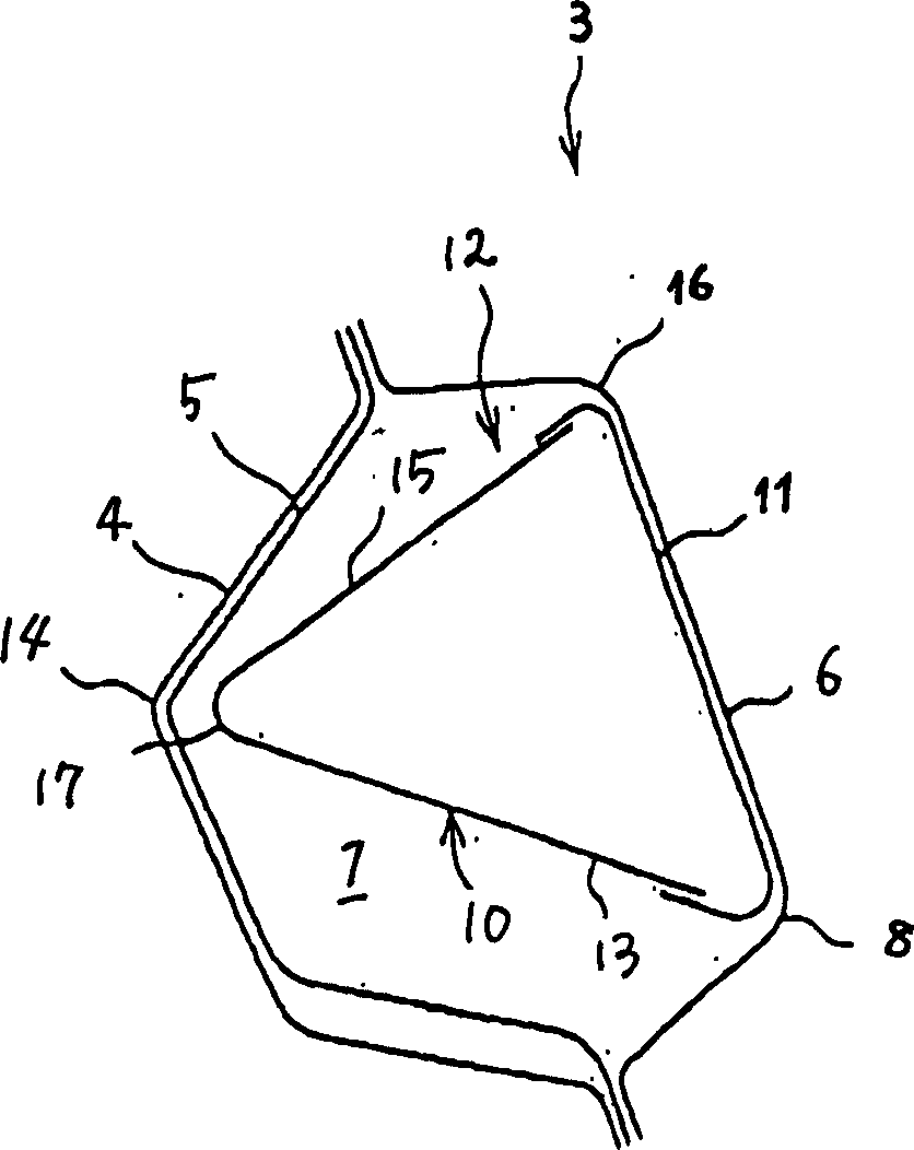
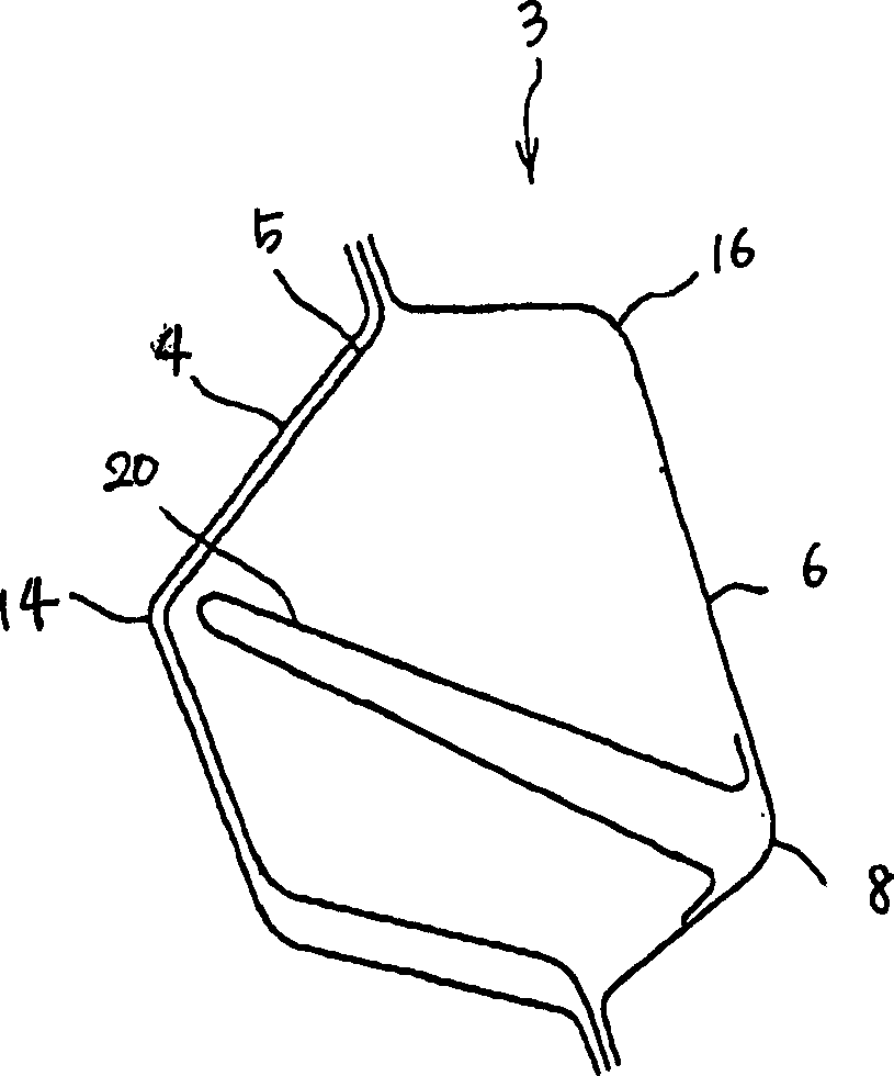
[0016] exist figure 1 and figure 2 In the shown first embodiment, the corner portion 3 where the front support beam 1 of the vehicle body is connected to the roof side rail 2 has a cross-section that is inclined with respect to the up, down, front and rear directions, and has an outer panel 4 and a slanting frame 5 that are superimposed on each other, and an inner panel 6 jointed, substantially polygonal hollow section 7 . In the range of part A extending from the front support beam 1 to the upper side beam 2 through the corner portion 3, the reinforcing member...


PUM


Abstract

To effectively increase the strength of the framework of a large size vehicle, a reinforcing member (12) with a substantially closed, triangular cross-section is arranged in a polygonal hollow cross-section (7) at the corner (3) of a front post (1) and top rail (2) for connecting the vehicle. The edges (13, 15) of the reinforcing member (12) transect the hollow cross-section (7) at the vicinity of the crest lines (8, 16) of the hollow cross-section (7) respectively, and then extend to the vicinity of the crest line (14) at the top front side of the vehicle.

Description

technical field [0001] The invention relates to the frame structure of the vehicle body, especially the structure of the connection part between the front support beam and the upper side beam. Background technique [0002] Such as figure 1 As shown in FIG. 7 , in the conventional vehicle body, the front frame and the roof side rail are connected at the corner 3 . The cross-section of the corner portion 3 is inclined with respect to the up-down and front-rear directions, and joined with the superimposed outer plate 4, slanted frame 5, and inner plate 6 to form a substantially polygonal hollow cross-section 7. In this conventional vehicle body frame structure, when the front of the vehicle collides and a large impact force is applied from the front of the vehicle, as shown by the dashed-two dotted line in FIG. The phenomenon that the part 8 is bent inward and the polygonal shape is broken. Therefore, the body frame may be bent toward the rear of the vehicle at the corner po...

Claims


Application Information

Patent Timeline
IPC IPC(8): B62D23/00B62D25/00B62D31/02
Inventor 内田隆信池田刚小林正则
Owner MITSUBISHI MOTORS CORP
Why Eureka
Try Eureka