Coiling apparatus of yarn

A yarn winding machine and yarn technology, which is applied in spinning machines, textiles and papermaking, and conveying filamentous materials, etc., can solve problems such as excessive tension and disconnection of yarns

Inactive Publication Date: 2004-09-22
MURATA MASCH LTD
View PDF3 Cites 5 Cited by
  • Summary
  • Abstract
  • Description
  • Claims
  • Application Information

AI Technical Summary

Problems solved by technology

As a result, the yarn may be over-tensioned to the point of breaking

Method used


Image

  • Coiling apparatus of yarn
  • Coiling apparatus of yarn
  • Coiling apparatus of yarn

Examples


no. 1 example

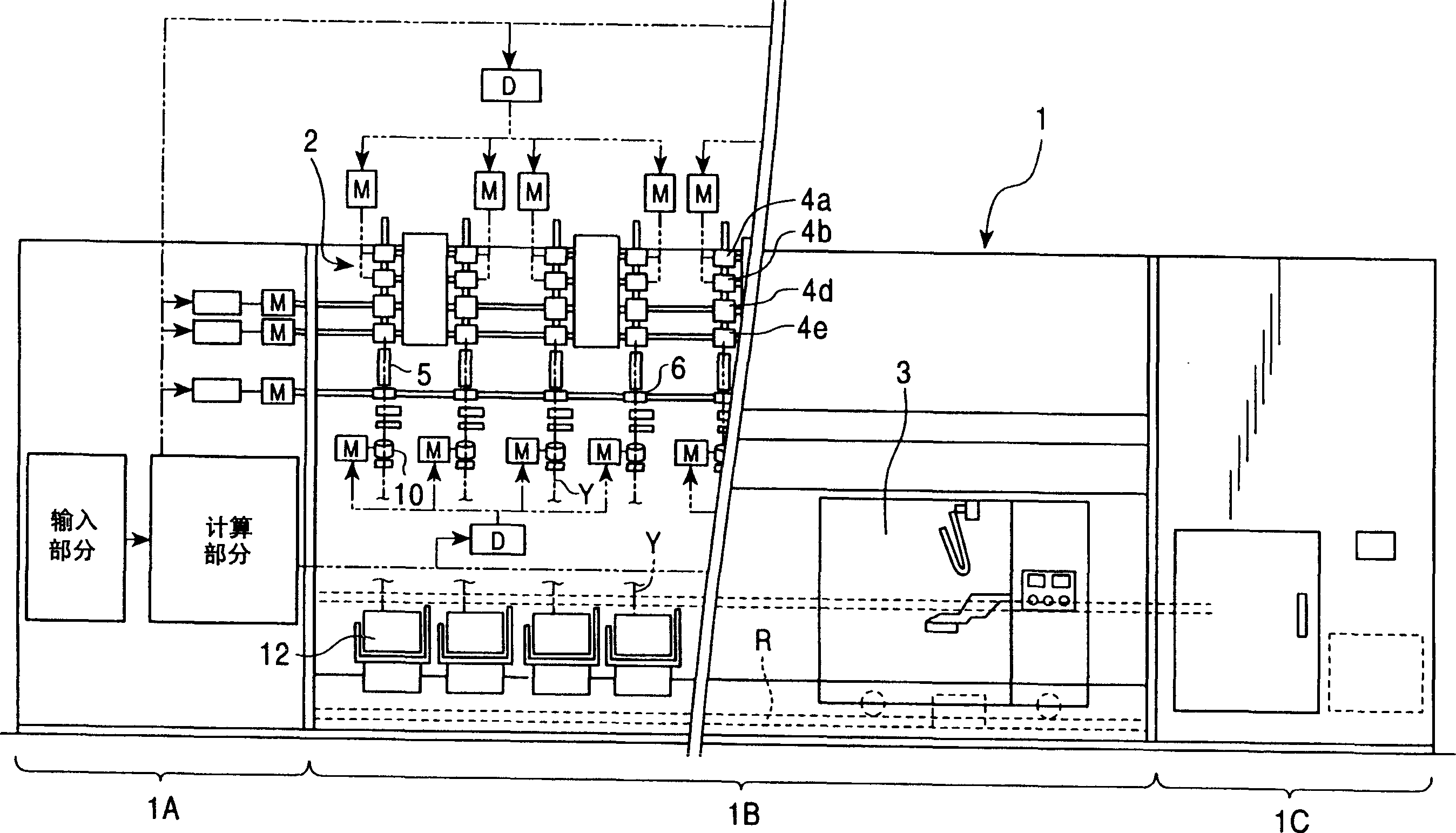
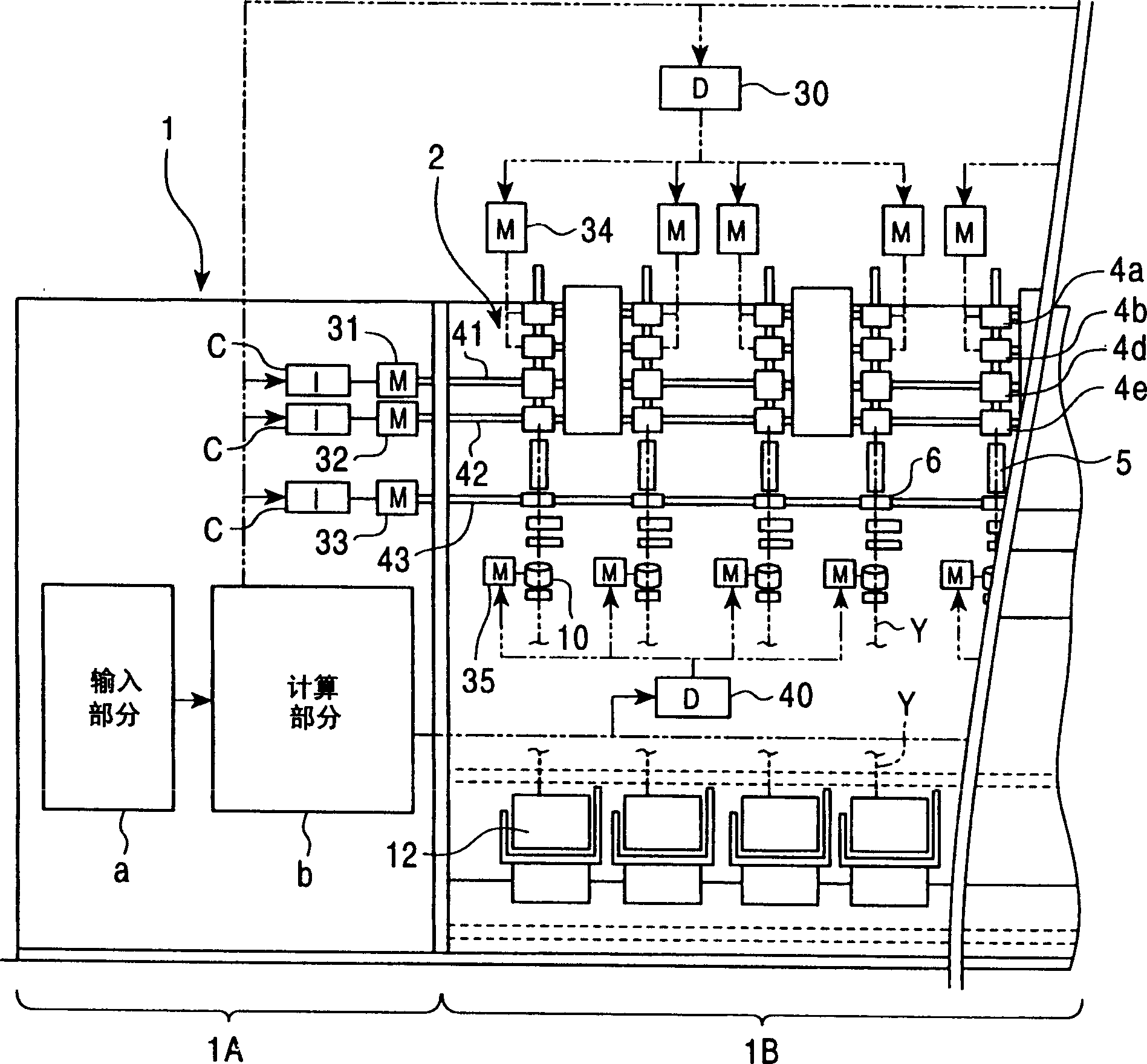
[0040] figure 1 It is a front view of an example of the spinning machine 1 used in the present invention. figure 2 is an enlarged view schematically showing a part of the internal structure of the spinning machine 1 . The spinning machine 1 is constituted by, for example, an air spinning machine. The main components of the spinning machine 1 include a control section 1A, a spinning section 1B in which a large number of spinning units 2 are arranged in line, a blower section 1C, and a work cart 3 including a yarn Splicing device (yarn splicing device), and is suitable for running freely along the track R between the spinning units 2.

[0041] The control section 1A controls the operation of the drive motors 31, 32, 33 for the drive shafts 41, 42, 43, the operation of the motors 34, 35 for the respective spinning units 2, the operation of the winding device 12, etc., among which The driving shafts 41, 42, 43 apply a driving force to all the spinning units 2 constituting the ...

no. 2 example

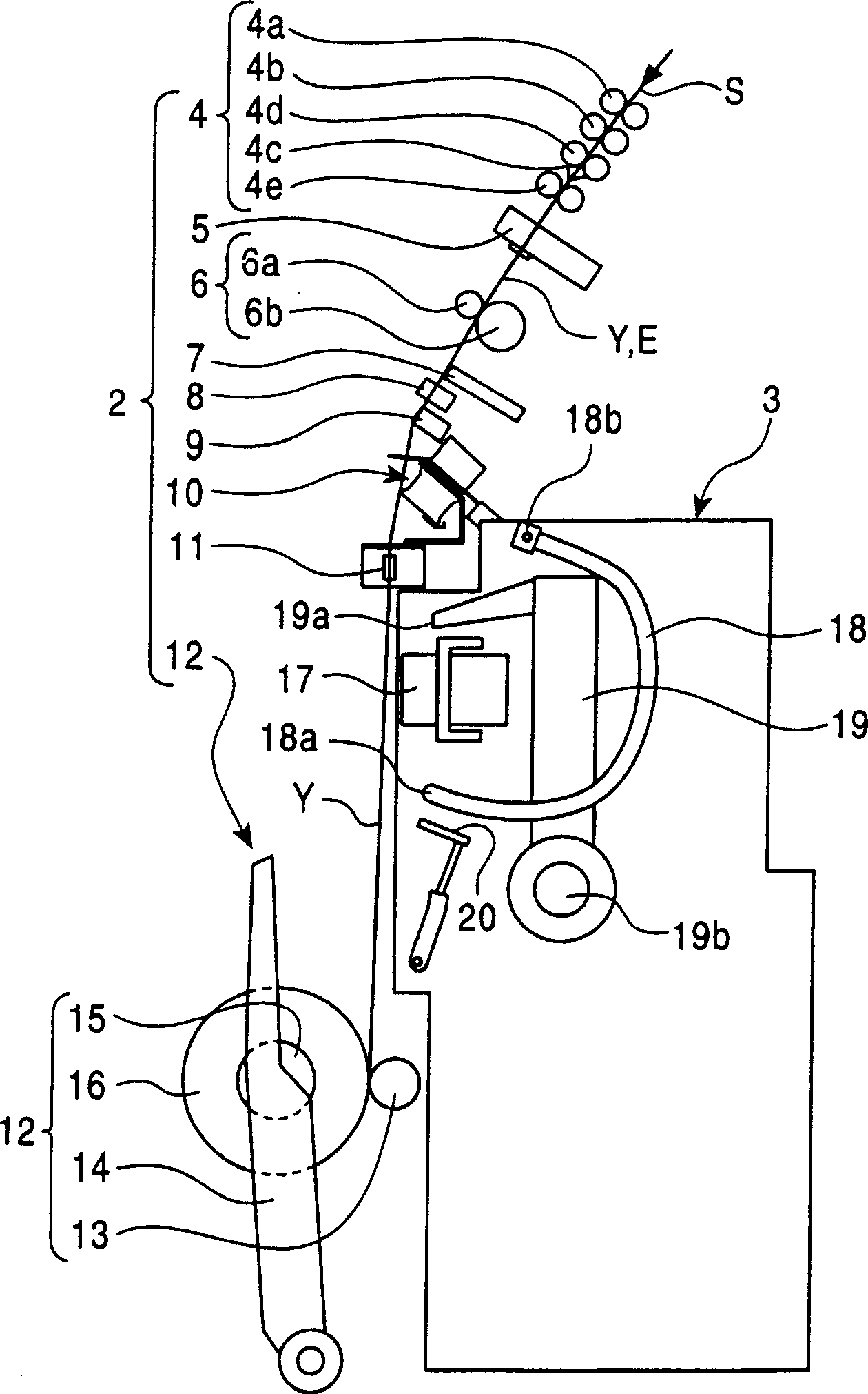
[0079] In the yarn slack eliminating device 10 according to the present invention, the upstream side yarn guide member 23 of the slack eliminating roller 21 may be fixed, and the downstream side yarn guide member 36 may be movable, such as Figure 19 shown. However, in view of the aforementioned configuration in which the upstream-side yarn guide member 23 is closer to the yarn defect detector 9 than the downstream-side yarn guide member 23, if it is satisfied that the yarn Y is removed from the yarn defect detector 9 just before the slack is eliminated condition, the upstream side yarn guide member 23 is preferably pushed forward to bend the yarn Y in the process of removing the yarn from the yarn defect detector 9 . This operation reduces the movement stroke compared to the operation in which the downstream-side yarn guide member 36 is reciprocated, and can prevent the member from protruding excessively.

[0080] However, instead of the operation of the yarn defect detector...

no. 3 example

[0082] Embodiments of the present invention are not limited to the above aspects. In the above description, the present invention is applied to a spinning machine having a plurality of spinning units. However, the present invention is also applicable to single-spindle type spinning machines. In the first embodiment described above, the yarn splicing device 17 is mounted on the work trolley 3 and this single yarn splicing device 17 performs the yarn splicing operation on all the spinning units 2 . However, a configuration in which the yarn splicing device 17 is provided for each spinning unit 2 may also be employed. In this case, the work cart 3 can be omitted. On the contrary, the yarn slack eliminating device 10 may be installed on the work cart 3 so that the single yarn slack eliminating device 10 can perform the yarn slack eliminating operation on all the spinning units. Also, in the examples described above, the present invention is used in a spinning machine designed i...


PUM


Abstract

The present invention prevents a yarn from being excessively tensed and broken owing to an increase in yarn tension when the yarn is wound around a slack eliminating roller during a yarn splicing operation. A yarn threading member is arranged at a position where it can engage with a yarn on the shortest yarn path between an upstream side guide and a downstream side guide arranged upstream and downstream, respectively, of a slack eliminating roller. The upstream side guide constitutes yarn moving means for moving the yarn from the shortest yarn path to a yarn path on which the yarn does not engage with the yarn threading member. If a yarn splicing operation is to be performed, then before the start of the operation, the yarn moving means holds the yarn away from the yarn path corresponding to the shortest distance and at a position at which the yarn does not engage with the yarn threading member. Then, immediately before the yarn splicing operation, the yarn is moved to the position of the yarn path corresponding to the shortest distance and is then engaged with the yarn threading member. Accordingly, the direction of the operation of engaging the yarn with the yarn threading member does not involve an increase in yarn tension. Therefore, the yarn can be reliably prevented from being excessively tensed and broken.

Description

technical field [0001] The present invention relates to a yarn winding machine comprising a yarn slack eliminating device for eliminating gaps between the supply side and the winding device during the yarn splicing operation. Possible yarn slack. Background technique [0002] In a high-speed spinning machine such as an air spinning machine, if a yarn defect is detected, the defective yarn portion is cut and removed by a cutter. The yarn splicing device then splices the yarn front, which is continuously fed by the spinning device, with the yarn tail on the yarn drum. This yarn splicing operation is performed while the yarn winding is kept stopped. Therefore, in order to eliminate the slack of the yarn continuously fed by the spinning equipment, the method used so far is to use a suction pipe called a slack pipe as described in Unexamined Japanese Patent Application Publication No. 2001-159039 to pick up excess slack in the yarn. [0003] However, since the total amount of...

Claims


Application Information

Patent Timeline
Patent Type & Authority Applications(China)
IPC IPC(8): B65H51/22B65H59/18B65H69/00D01H13/10
CPCB65H2701/31B65H59/18B65H69/00B65H51/22B65H57/003D01H13/104
Inventor 平尾修重山昌澄八木宏幸泽田晴稔
Owner MURATA MASCH LTD
Why Eureka
Try Eureka