Device for supplying material

The technology of a feeding device and a locking device is applied in the directions of transportation and packaging, conveyors, grain processing, etc., which can solve the problem of high overall height of the feeding device, and achieve the effects of simple structure, low overall height, and reduced manufacturing and installation costs.

Inactive Publication Date: 2004-09-22
LOESCHE GMBH
View PDF2 Cites 0 Cited by
  • Summary
  • Abstract
  • Description
  • Claims
  • Application Information

AI Technical Summary

Problems solved by technology

Due to the stacked coal bunkers and the three conveyor lines positioned horizontally, the overall height of the entire supply unit is high and requires corresponding infrastructure, installation and energy costs

Method used


Image

  • Device for supplying material
  • Device for supplying material
  • Device for supplying material

Examples


Embodiment Construction

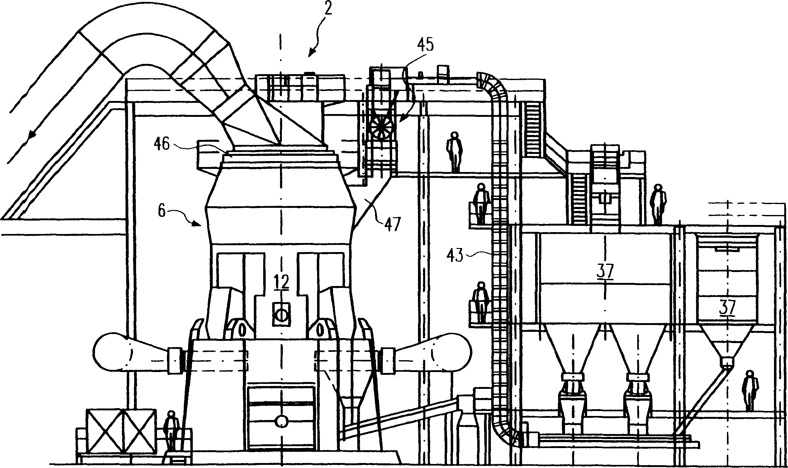
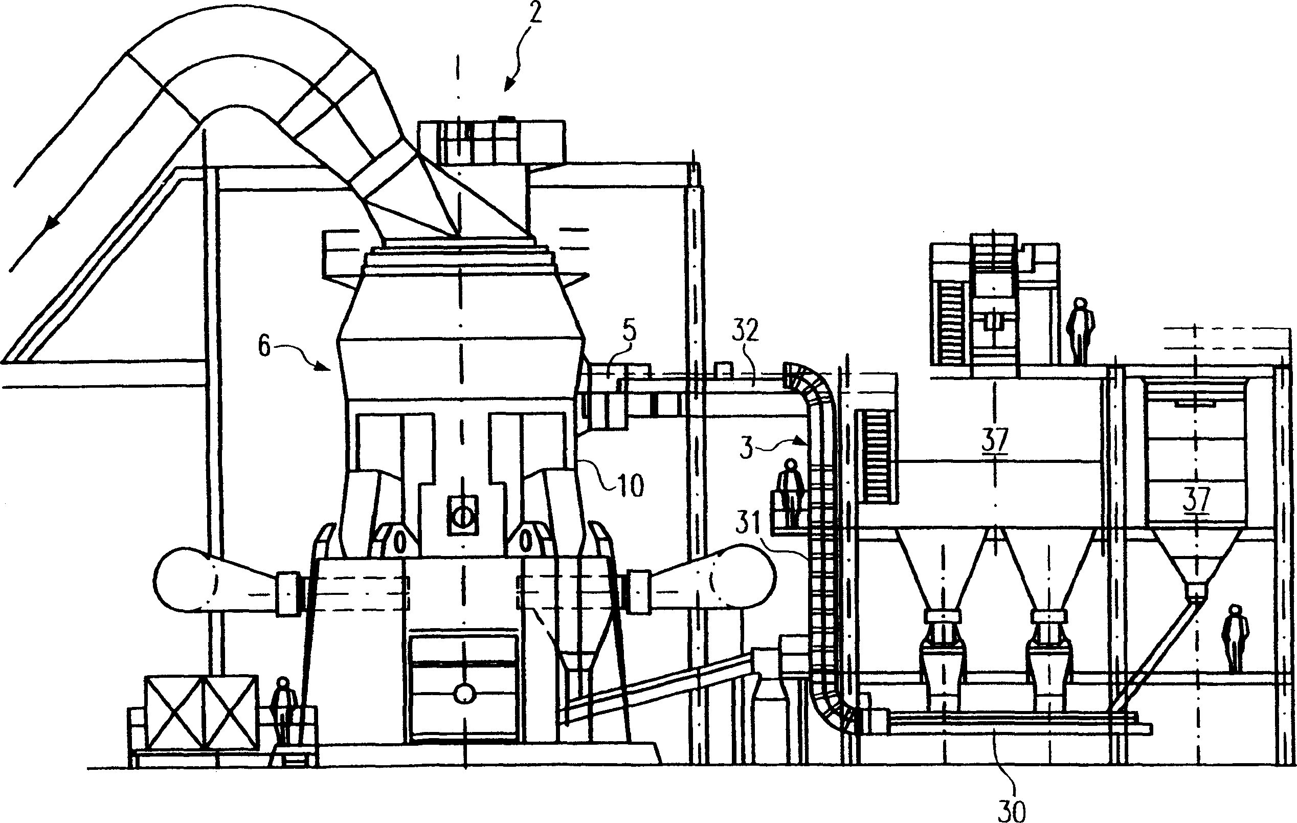
[0028] shown in figure 2 A partial view of the milling plant 2 is somewhat similar to that shown in figure 1 are the same as in the prior art, such as the pneumatic discharge roller mill as the vertical mill 6 with air flow conveying and the silo 37 in which the material to be crushed in the vertical mill 6 is stored. The feeding device according to the invention has a double belt conveyor 3 as a conveyor and a feeding device for the material, not shown, which is fed by the double belt conveyor 3 , a blocking device adapted to this feeding device , hereinafter referred to as the sandwich locking device 5 .

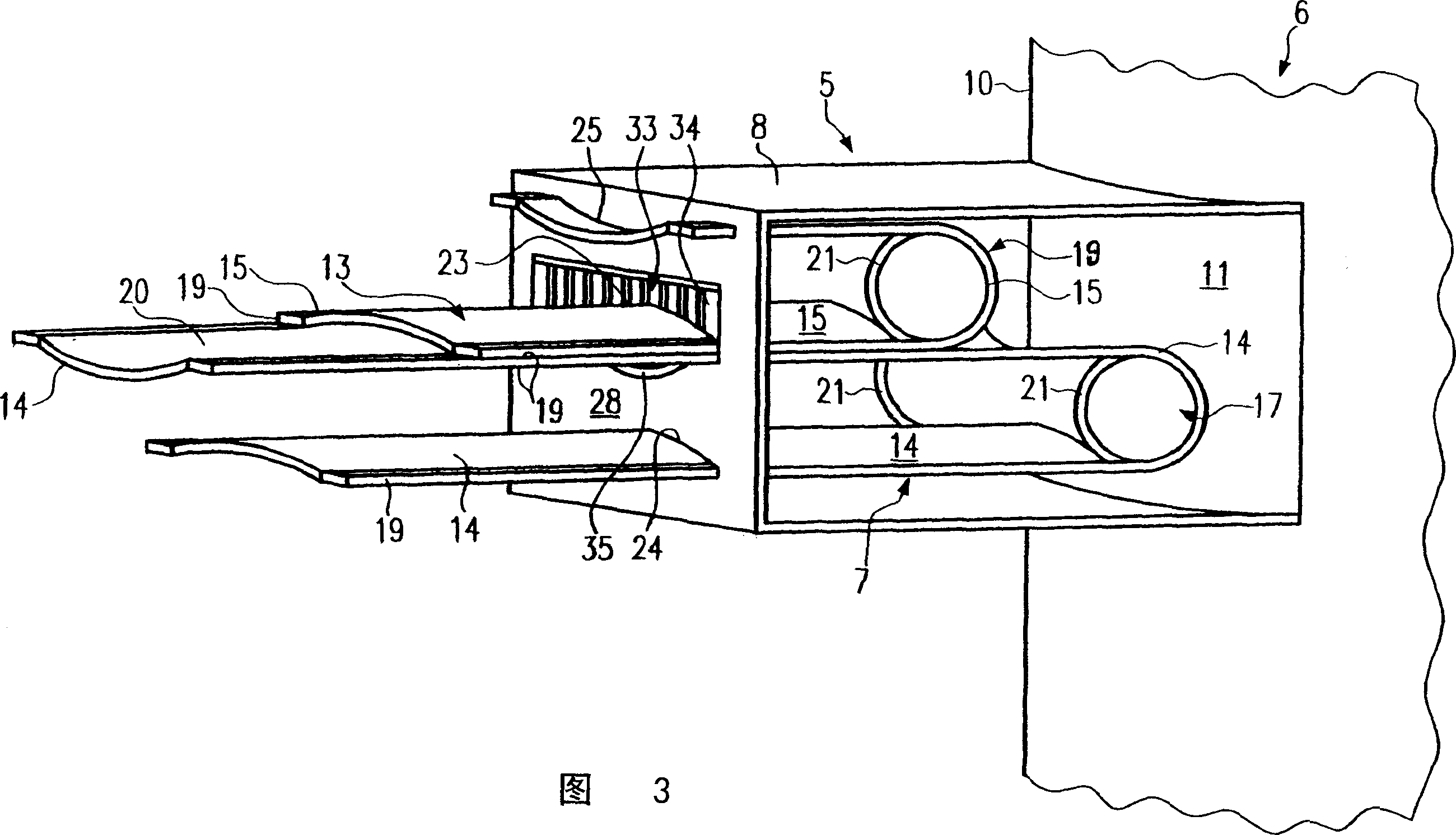
[0029] The above-mentioned sandwich locking device 5 is fastened to the casing 10 of the vertical mill 6 in a gas-tight and / or pressure-tight manner in the vicinity of the feed hole 11 (see FIG. 3 ).

[0030] Compare figure 1 The prior art milling equipment in the figure 2 A grinding plant with a feeding device according to the invention, which has a sandwich-type lo...


PUM


Abstract

A device for supplying material to a container, particularly for supplying raw material to a vertical mill with air flow conveying in a milling plant. A conveyor is provided for the material, whereof an end region is located in a feed device. The feed device and the end region of the conveyor located therein are incorporated into the pressure system of the container or the vertical mill. The feed device can be constructed as a sandwich lock and the conveyor as a double strap belt conveyor for the material to be supplied.

Description

technical field [0001] The present invention relates to a device for feeding material to a container according to the preamble of claim 1 . [0002] The present invention is particularly suitable for loading or filling containers and installations with materials in which materials are stored, handled or processed under overpressure or underpressure. [0003] The best field of application is milling plants, where the raw material is supplied by means of conveying and feeding means for milling to a vertical mill, such as a pneumatic discharge roller mill, by means of air conveying. Background technique [0004] In order to load the raw materials to be pulverized, such as pre-dried lignite or cement clinker and slag into vertical mills, it is known to use two or three hasp locks or a bucket wheel lock, which ensure that the or seals required for pneumatic discharge mills operating under negative pressure. [0005] However, the disadvantage is that these material locks are cos...

Claims


Application Information

Patent Timeline
Patent Type & Authority Applications(China)
IPC IPC(8): B02C1/00B02C23/02
CPCB02C23/02
Inventor T·勒舍
Owner LOESCHE GMBH
Why Eureka
Try Eureka