

Driving circuit of vacuum fluorescent display
A technology for driving circuits and displays, applied in static indicators, instruments, telephone communications, etc., can solve problems such as filament damage, increase the processing load of the external controller 40, etc., and achieve the effect of improving reliability
- Summary
- Abstract
- Description
- Claims
- Application Information
AI Technical Summary
Problems solved by technology
Method used
Image

Examples
no. 1 example
[0061] === Abnormal state detection unit ==
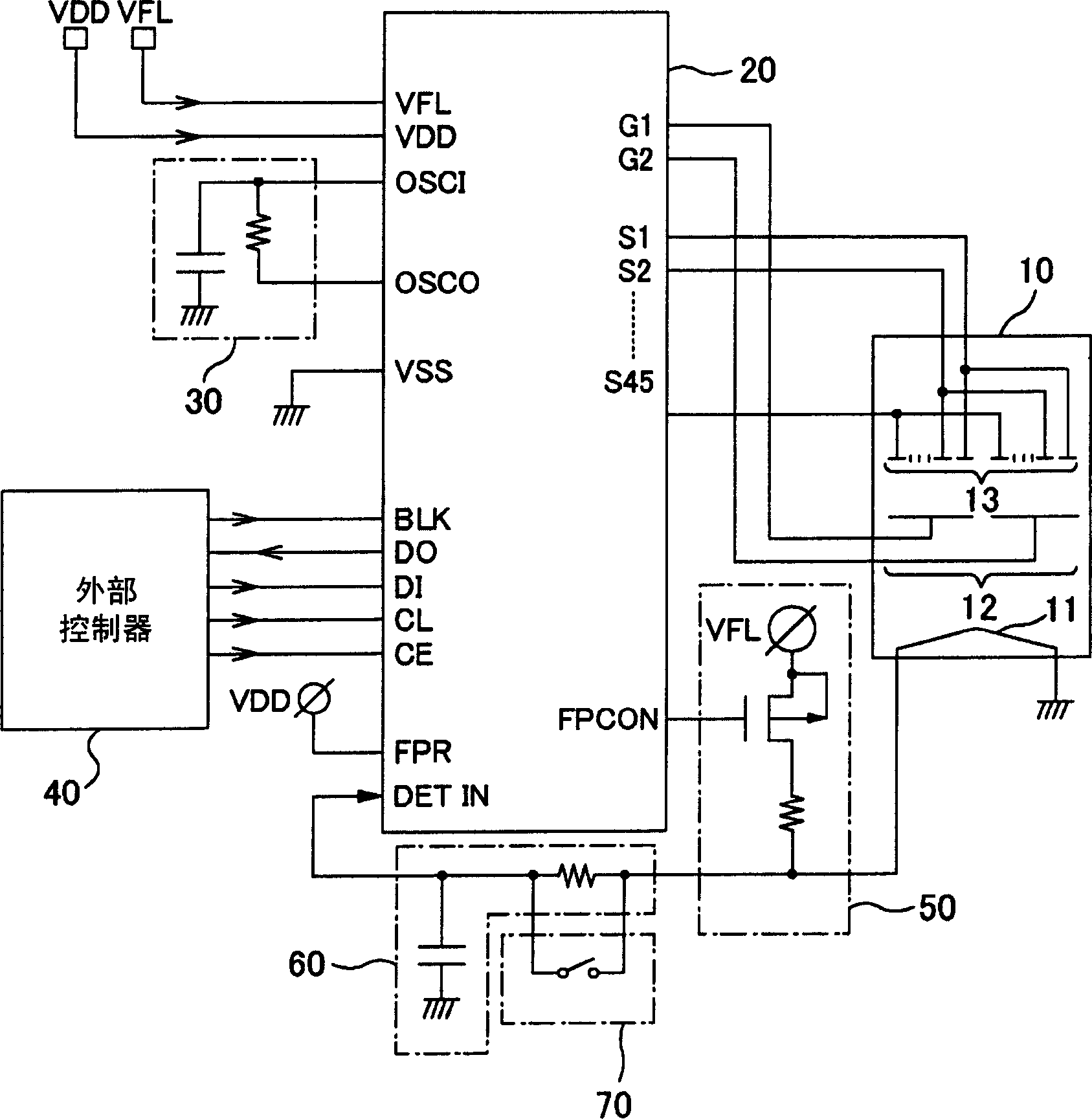
[0062] Reference Figure 4 The circuit structure of the abnormal state detection unit 213 as the first embodiment of the present invention will be described.
[0063] As shown in the figure, the abnormal state detection unit 213 has a pulse detection unit 80, a level detection unit 90, and a selection unit 100.
[0064] The pulse detection unit 80 detects that the level of the filament pulse voltage is fixed according to the number of pulses of the filament pulse voltage input from the DETIN terminal for each predetermined time period TP.
[0065]The level detection unit 90 detects that the level of the filament pulse voltage is fixed based on the level of the direct current (DC) rectified voltage generated by integrating the filament pulse voltage input from the DETIN terminal.
[0066] The level of the DC rectified voltage is set in a low range of about "5-20%" with respect to the duty ratio of the filament pulse voltage, because the...
no. 2 example
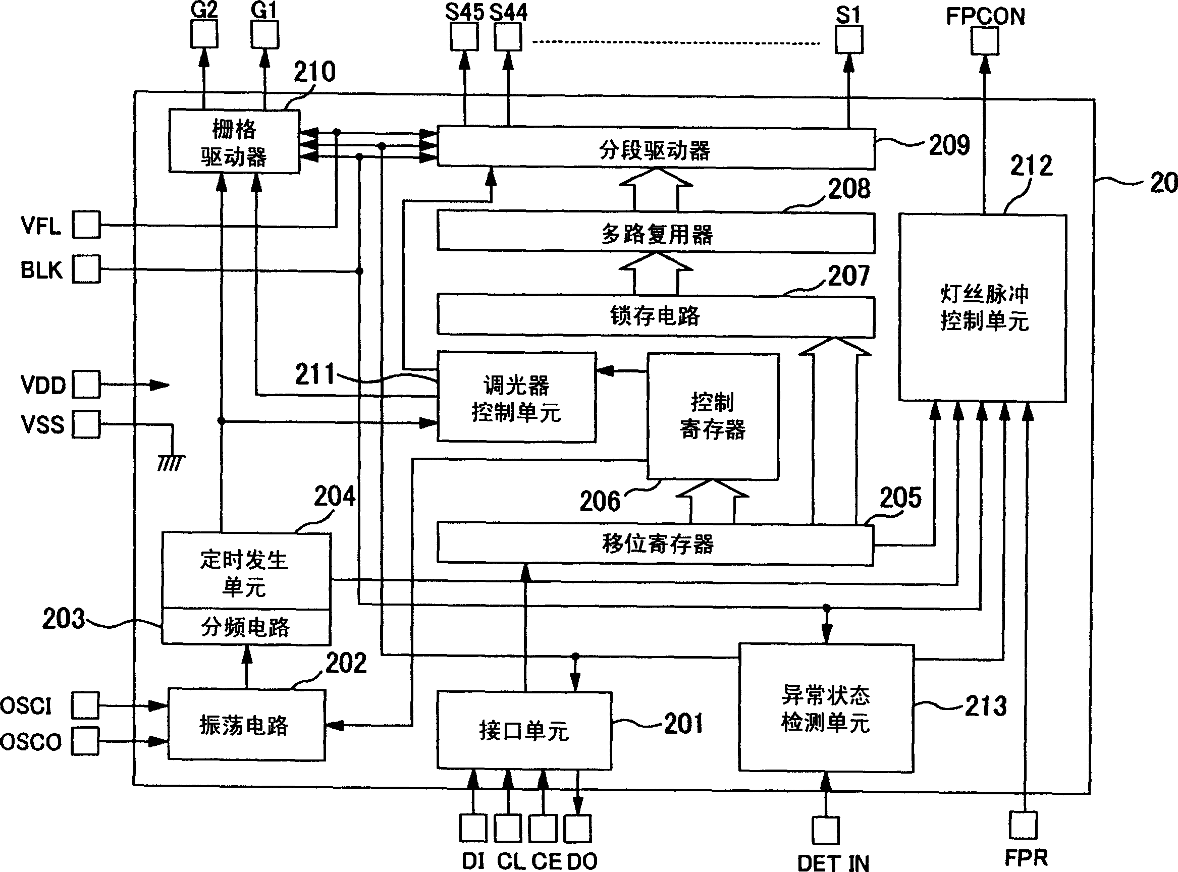
[0102] The VFD drive circuit 20 according to the second embodiment of the present invention controls the output of at least one of the segment driver 209, the grid driver 210, and the filament pulse control unit 212 according to the output of the abnormal state detection unit 213 (abnormal state detection signal), The driving of at least one of the segment electrode 13, the grid electrode 12, and the filament 11 is terminated.
[0103] The operations of the above-mentioned controlled segment driver 209, grid driver 210, and filament pulse control unit 212 will be described separately.
[0104] == Control of the output of the grid driver or segment driver ==
[0105] Reference Figure 7 , The operation of the segment driver 209 or the grid driver 210 based on the abnormal state detection signal (the output of the abnormal state detection unit 213) will be described. In the following description, the description of the grid driver 210 that performs the same operation as the segment ...
PUM
 Abstract
Description
Claims
Application Information