Supercharge Your Innovation With Domain-Expert AI Agents!

Magnetoresistance effect type magnetic head and its mfg. method

A magnetoresistance and magnetic head technology, which is applied in the manufacture of magnetic flux-sensitive magnetic heads, magnetic recording heads, magnetic recording, etc., can solve the problems of not disclosing the means of returning the reversed magnetic moment to the original direction, and not disclosing the specific method of damage, etc.

Inactive Publication Date: 2004-10-06
HITACHI GLOBAL STORAGE TECH JAPAN LTD
View PDF4 Cites 2 Cited by
  • Summary
  • Abstract
  • Description
  • Claims
  • Application Information

AI Technical Summary

Problems solved by technology

However, in the above-mentioned known examples, there is no specific structural means for returning the reversed magnetic moment to the original direction.
In addition, in Patent Document 4, various researches have been carried out on "a spin-valve magnetic head having a laminated pinned layer having an exchange bonding layer", but there is no specific method for recovering damage to the magnetic structure of the pinned layer at room temperature. and the structure of the specific magnetic head suitable for the recovery

Method used


Image

  • Magnetoresistance effect type magnetic head and its mfg. method
  • Magnetoresistance effect type magnetic head and its mfg. method
  • Magnetoresistance effect type magnetic head and its mfg. method

Examples


Embodiment 1

[0051] Although this embodiment can be widely used in detecting external magnetic fields (for example, as a sensor), it refers here to a read head that is particularly useful for information recording and reading systems. Information is recorded as a distribution of magnetic domains. As the magnetic recording medium, any kind of medium can be used, for example, a magnetic tape, a magnetic drum, one or more hard disks, and the like. The magnetic regions are usually arranged along the track, and the structure of the track can be circular, spiral, spiral, or indefinite in length.

[0052] Figure 13 An example of a typical information recording and reading device is shown. The electronic computer 1 accepts input information through an input device 2 having one or more interfaces between a network, a keyboard, a scanner, or their equivalents. In addition to being connected to one or more input devices 2 , the computer 1 can also output to one or more output devices 3 . As the ...

Embodiment 2

[0211] Figure 8 The specific structure of the readout sensor representing another embodiment of the present invention will be described in detail later, refer to Figure 8 In terms of its structure, the spin-valve film 18 has a first ferromagnetic layer (hereinafter referred to as a free layer, corresponding to, for example, the CoFe film 44 and the Permalloy film 45 ) that is relatively easy to respond to a magnetic field, and is difficult to respond to a magnetic field. The second ferromagnetic layer (hereinafter referred to as a pinned layer, corresponding to the stacked pinned layer 50), and a conductive nonmagnetic spacer layer (for example, corresponding to the Cu film 43) between them. In addition, under the fixed layer, there is a substrate layer 42 for adjusting the crystal morphology and for increasing the resistance change. Furthermore, a capping layer (for example, corresponding to the Ta capping layer 46 ) is formed on the free layer composed of 44 and 45 .

[...

Embodiment 3

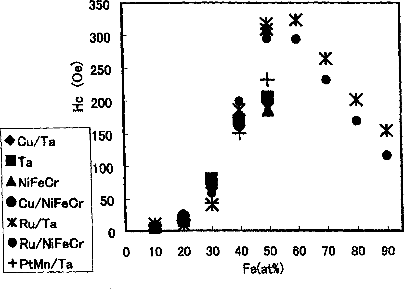
[0254] In Example 1 and Example 2, in order to increase the coercive force of the ferromagnetic film and make the composition of CoFe within an appropriate range, as another method, there is a method of adding additional elements to Co or CoFe. Elements to be added include elements such as Cr and V.


PUM

PropertyMeasurementUnit
thicknessaaaaaaaaaa

Abstract

A magnetoresistive head in which a pinned layer comprises two films, i.e., a ferromagnetic film A and a ferromagnetic B anti-ferromagnetically coupled to each other and a anti-ferromagnetic coupling film for separating the two ferromagnetic films A and B, where the coercivity of the ferromagnetic film alone is 200 (Oe) or more and the coercivity of the ferromagnetic film alone is 20 (Oe) or less. The compositions for the ferromagnetic film A and the ferromagnetic film B, when expressed by Co100-YFeY (at %) are: ferromagnetic film A: 80>=Y>=40, and ferromagnetic film B: 20>=Y>=0, where the material for the film in contact with the ferromagnetic film A is Ru, Ta, NiFeCr, Cu or NiFe.

Description

technical field [0001] The present invention relates to a magnetoresistance (MR) effect type magnetic head, a manufacturing method, a magnetic recording and reproducing device using the magnetic head, and a magnetoresistance (MR) sensor. Background technique [0002] In recent years, with the high density of magnetic recording devices, spin valve type magnetoresistive sensors have been adopted as sensors for reproduction. A spin valve type sensor is disclosed in Patent Document 1 - US Pat. No. 5,159,513. [0003] The essential feature of the spin-valve magnetoresistive sensor is that its basic structure has a ferromagnetic layer called a pinned layer, a ferromagnetic and soft magnetic layer called a free layer, and a direct contact with these two layers. Adjacent and in the middle of the conductive layer, the exchange bonding layer in direct contact with the fixed layer (that is, a multilayer structure with a sequence of free layer, conductive layer, fixed layer, and exchan...

Claims


Application Information

Patent Timeline
Patent Type & Authority Applications(China)
IPC IPC(8): G11B5/00G11B5/39
CPCG11B5/3903B82Y10/00G11B2005/0008Y10T29/49034
Inventor 西冈浩一重松惠嗣
Owner HITACHI GLOBAL STORAGE TECH JAPAN LTD
Features
  • R&D
  • Intellectual Property
  • Life Sciences
  • Materials
  • Tech Scout
  • Unparalleled Data Quality
  • Higher Quality Content
  • 60% Fewer Hallucinations
Learn More