Optical lighting system and image projection system containing it

A lighting system and image projection technology, applied in the field of projection systems, can solve problems such as increased manufacturing costs, reduced manufacturing and assembly capabilities, and difficulties in manufacturing and assembling total reflection prisms

Inactive Publication Date: 2004-10-13
SAMSUNG ELECTRONICS CO LTD
View PDF2 Cites 5 Cited by
  • Summary
  • Abstract
  • Description
  • Claims
  • Application Information

AI Technical Summary

Problems solved by technology

[0011] Therefore, it is difficult to manufacture and assemble the total reflection prism, which reduces the manufacturing and assembling capabilities, thereby increasing the manufacturing cost
Between the reflective display device and the projection optics, light beams reflected off the face of the fully reflective prism tend to enter the projection optics, which adversely affects image contrast

Method used


Image

  • Optical lighting system and image projection system containing it
  • Optical lighting system and image projection system containing it
  • Optical lighting system and image projection system containing it

Examples


Embodiment Construction

[0035] Embodiments of the invention will now be described in detail with reference to examples shown in the drawings, in which like reference numerals refer to like elements. The embodiments will be described below in order to explain the present invention by referring to the figures.

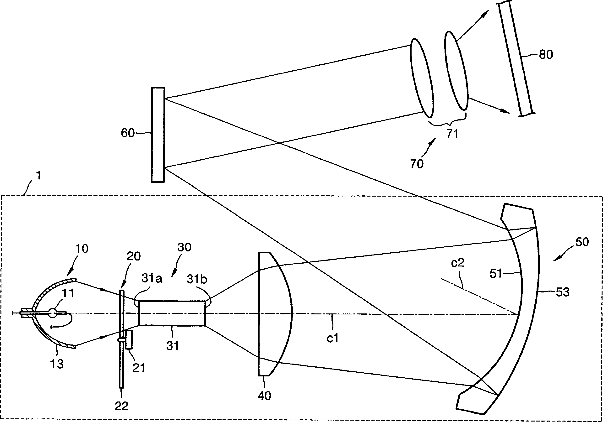
[0036] figure 1 An image projection system with an optical illumination system 1 according to an embodiment of the invention is represented. refer to figure 1 , the optical lighting system includes a light source 10, at least one lighting lens 40 and a Manin reflector 50, the Manin reflector 50 irradiates the light beam emitted from the light source 10 onto a predetermined reflecting device. In addition to the optical illumination system 1 , the image projection system also includes a reflective display 60 which is a predetermined reflection device, and a projection optical system 70 .

[0037] The light source 10 may be a lamp type. The lamp-type light source 10 includes a lamp 11 that emi...


PUM


Abstract

An optical illumination system and an image projection system including the same include a light source, at least one illuminating lens and a Mangin mirror that illuminate light emitted from the light source on a predetermined reflective device, the Mangin mirror including a concave refracting surface that refracts and transmits light incident from the illuminating lens, and a convex reflecting surface disposed behind the concave refracting surface to internally reflect the light refracted by the concave refracting surface back toward the concave refracting surface and tilted with respect to the illuminating lenses. The light reflected from the convex reflecting surface and then refracted through the concave refracting surface propagates along a path that is different from a path of the light emitted from the illuminating lens.

Description

technical field [0001] The present invention relates to an optical lighting system for emitting light onto a reflective display device having micromirrors that switch the light beam on or off by changing the reflection angle, and a projection system comprising the above system. [0002] This application claims priority from Korean Patent Application No. 2003-21621 filed in the Korean Intellectual Property Office on Apr. 7, 2003, the disclosure of which is hereby incorporated by reference. Background technique [0003] Generally, an image projection system applied to a rear projection television or a projector for front projection includes an optical lighting system, a display device, and a projection optical system. The display device modulates light beams irradiated by the optical illumination system, and the projection optical system projects the modulated light beams to display enlarged images. [0004] Projection systems have evolved to use digital beam processing (DLP)...

Claims


Application Information

Patent Timeline
Patent Type & Authority Applications(China)
IPC IPC(8): G03B21/14F21S2/00F21V13/00G02B17/08G02B27/00G03B21/00
CPCG02B19/0066G02B17/08G02B19/0028G02B17/0856G02B19/0047G02B17/0864G02B27/00
Inventor 车荣德
Owner SAMSUNG ELECTRONICS CO LTD
Why Eureka
Try Eureka