Luminous device and method of reducing fluorescent tube image of luminous device

A technology of light-emitting devices and lamp tubes, which is applied in the field of light-emitting devices and lightening tube images of light-emitting devices, which can solve problems such as low luminous efficiency, deterioration of luminous efficiency, and increased power consumption, and achieve the effect of uniform light-emitting surface

Inactive Publication Date: 2004-10-13
NEC LCD TECH CORP
View PDF1 Cites 0 Cited by
  • Summary
  • Abstract
  • Description
  • Claims
  • Application Information

AI Technical Summary

Problems solved by technology

[0009] For the diffuser installed, it is indispensable to obtain the desired luminous quality, but it has the disadvantage of causing low luminous efficiency
[0010] In other words, for the diffuser plate, because the light emitted from the lamp tube is not reflected but absorbed by the diffuser plate, it will have good luminous quality, but its luminance will decrease and the luminous efficiency will deteriorate.
In particular, the diffusion agent used in the diffusion plate has low luminous efficiency due to light absorption
[0011] Also, although it is considered to increase the number of lamp tubes to increase the brightness and reduce the distance between adjacent lamp tubes, so as to increase the brightness and reduce the image of the lamp tubes, the increase in the number of lamp tubes will lead to an increase in power consumption

Method used


Image

  • Luminous device and method of reducing fluorescent tube image of luminous device
  • Luminous device and method of reducing fluorescent tube image of luminous device
  • Luminous device and method of reducing fluorescent tube image of luminous device

Examples


Embodiment

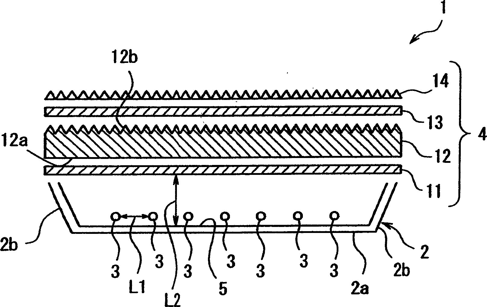
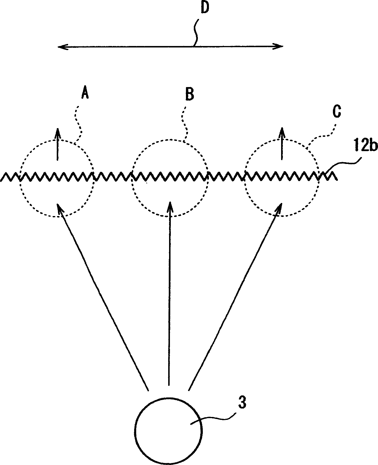
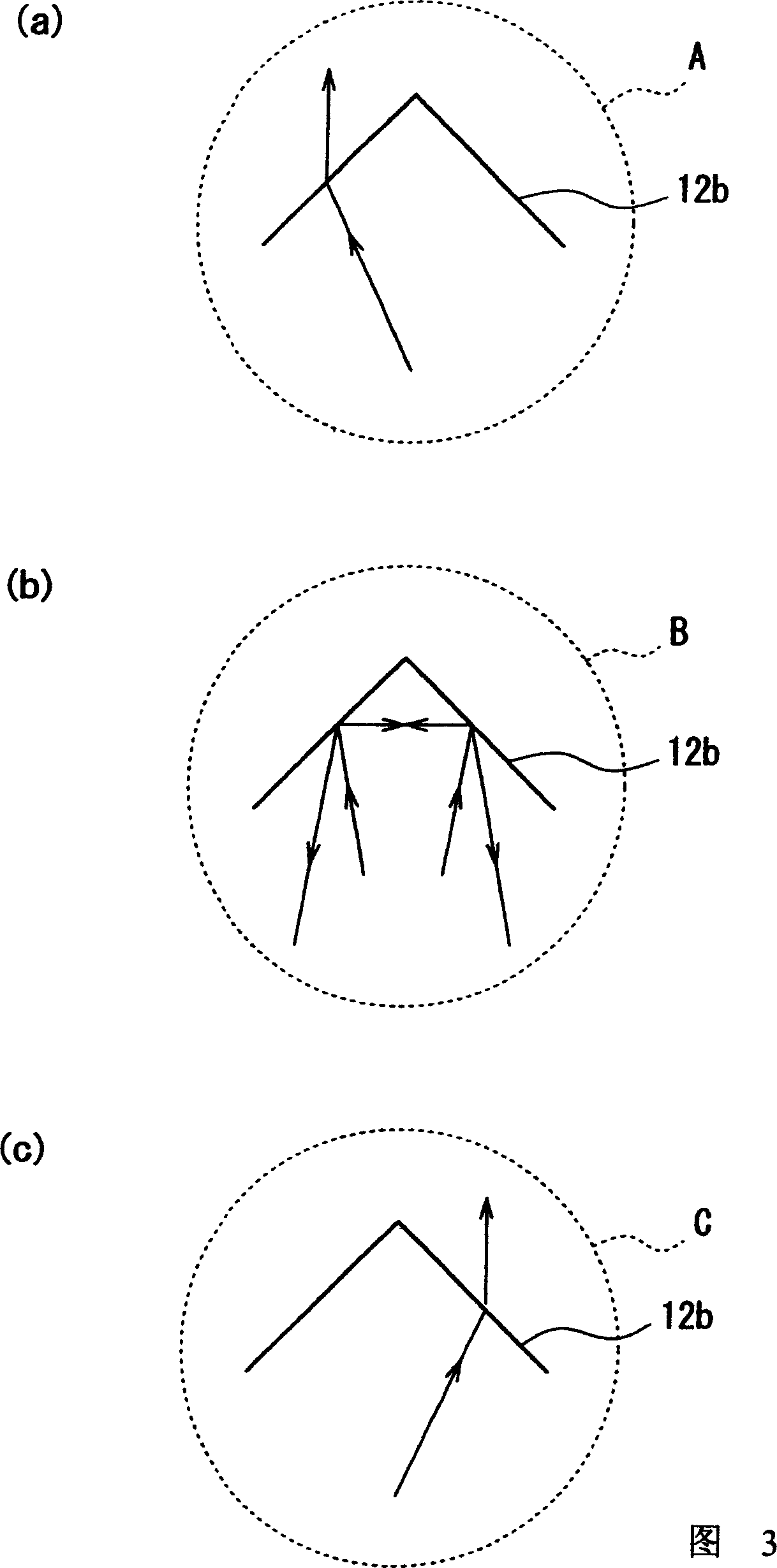
[0064] exist figure 1 In the direct-type backlight shown, the housing 2 is made of aluminum with a thickness of 1.0 mm, the lamp tube 3 is a cold cathode lamp tube with a diameter of 3 mm, the reflective film 5 is E60V manufactured by Toray, and the first diffuser film 11 is made of Kewa Co., Ltd. ) manufactured BS-04, the transparent plate 12 is a transparent plate of acrylic acid with a thickness of 2mm, the light-incident surface 12a of the transparent plate 12 is a concave-convex surface formed by sandblasting, and the light-emitting surface 12b of the transparent plate 12 is a vertex angle of 100°. Triangular protruding strips, the width of each protruding strip (the length of the base of the triangle) is a prism surface of 70 μm, the second diffusion film 13 is BS-04 manufactured by Huihe Co., Ltd., and the lens film 14 is BEFII90 manufactured by 3M / 50, the tube spacing L1 is 25mm, the distance L2 between the light-emitting surface structure 4 (the first diffusion film ...


PUM

PropertyMeasurementUnit
thicknessaaaaaaaaaa

Abstract

Provided is a new technical means for relaxing a lamp image while preventing luminance degradation. This light emitting device (1) composed by installing a lamp (3) behind its light emitting surface is equipped with: diffusion films (11 and 13) used as blurring parts for blurring the lamp image by diffusing light from the lamp (3) to a level leaving the lamp image; and lens parts (12b and 14) for increasing the number of the blurred lamp images in the surface direction by lenses.

Description

technical field [0001] The present invention relates to a light-emitting device such as a direct-type backlight for a liquid crystal display device and a method for reducing the tube image of the light-emitting device. Background technique [0002] A liquid crystal display device includes a liquid crystal panel and a backlight that illuminates the liquid crystal panel. As the backlight, it is a direct type backlight composed of several cold cathode lamps arranged behind the diffuser plate. The aforementioned diffuser plate is a white plate with a thickness of several millimeters mixed with a diffuser. [0003] For the direct type backlight, the light emitted from the cold cathode lamp is diffused by the diffusion plate to obtain a planar light emitting surface. [0004] When the light emitted from the lamp tube passes through the diffusion plate, the light is diffused by the diffusing agent inside the diffusion plate. [0005] In addition, the diffusion plate usually has ...

Claims


Application Information

Patent Timeline
Patent Type & Authority Applications(China)
IPC IPC(8): G02F1/13357F21S2/00F21Y103/00G02F1/1335
Inventor 羽生笃史
Owner NEC LCD TECH CORP
Why Eureka
Try Eureka