Portable electronic equipment and power supply control method

A technology of electronic equipment and power control, applied in data processing power supply, chemical instruments and methods, television, etc., can solve problems such as battery consumption

Inactive Publication Date: 2004-10-13
CASIO COMPUTER CO LTD
View PDF0 Cites 13 Cited by
  • Summary
  • Abstract
  • Description
  • Claims
  • Application Information

AI Technical Summary

Problems solved by technology

[0004] Although there is a device that is automatically powered on by vibration, at this time, when the device is

Method used


Image

  • Portable electronic equipment and power supply control method
  • Portable electronic equipment and power supply control method
  • Portable electronic equipment and power supply control method

Examples


no. 1 approach

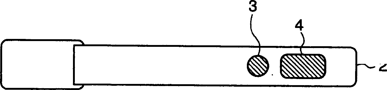
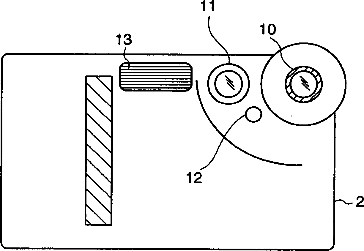
[0030] FIG. 1 shows the appearance structure of a digital camera common to this embodiment and each embodiment described later, Figure 1A means above, Figure 1B means the back side, Figure 1C is a structural view representing the front.

[0031] As shown in the figure, a power button 3 and a release button 4 are arranged on the top surface of the digital camera 1, which is a rectangular parallelepiped plate-shaped housing, that is, the camera body 2, near the right end.

[0032] The power key 3 is a key to switch the power on / off state, and the release key 4 not only performs shutter operation in the recording mode through its operation, but also has the function of selecting / executing according to the state displayed on the mode menu of various operations. key function.

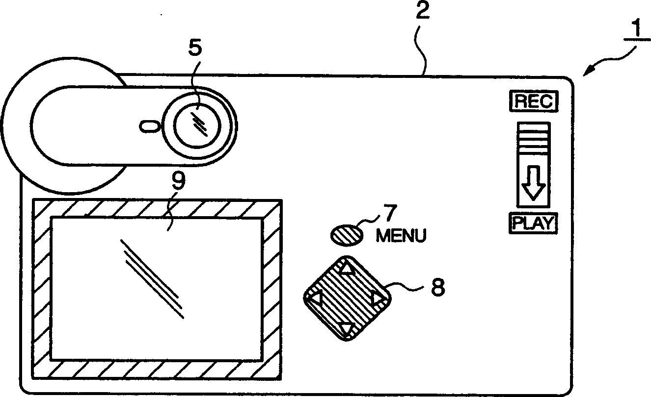
[0033] An optical viewfinder (finder), a recording (REC) / reproduction (PLAY) switch 6, a menu key 7, a cursor key 8 for selecting displayed menu items, etc., and a liquid crystal are disposed on the ba...

no. 2 approach

[0062] Next, a second embodiment of the present invention will be described. This embodiment also applies the present invention to a digital camera.

[0063] Figure 5 It is a block diagram showing the electrical configuration of the digital camera 201 of this embodiment. That is, in this digital camera 201 , an optical sensor 214 is provided instead of the direction sensor 14 in the first embodiment. The optical sensor 214 is a brightness detection device of the present invention for detecting the brightness around the camera body 2 , and is configured to send its detection output directly to the control unit 30 . As the photosensor 214, for example, a photoconductive cell (Cds cell or the like), a photodiode, a phototransistor, and a photocell can be used.

[0064] Below, according to Figure 6 The flow chart of FIG. 1 illustrates the operation of the digital camera 201 constructed as described above in relation to the present invention. Figure 6 It represents the oper...

no. 3 approach

[0073] Next, a third embodiment of the present invention will be described. This embodiment also applies the present invention to a digital camera.

[0074]FIG. 7 is a block diagram showing the electrical configuration of the digital camera 301 of this embodiment. That is, this digital camera 301 has a structure including the direction sensor 14 described in the first embodiment and the optical sensor 214 described in the second embodiment. Other configurations are the same as those described in the first embodiment.

[0075] Below, according to Figure 8 and Figure 9 The flow chart of FIG. 1 illustrates the operation of the digital camera 301 constructed as described above in relation to the present invention. This figure shows the operation related to the power control of the digital camera 301 after the power is turned off in the state of the snapshot mode set by the user.

[0076] When the digital camera 301 is in the power-off state, when the brightness around the c...


PUM


Abstract

A digital camera (1) is provided with a direction sensor (14) which senses a vertical or horizontal direction along a direction of rotation about a predetermined axis of the camera body. When the direction sensor (14) senses that the camera body is changed from a vertically laid state to a horizontally laid state or from a horizontally laid state to a vertical laid state in a power source off state with a predetermined operation mode being set, a control unit (30) switches on the power source. If no operation is made during a short time period after the power source is switched on, the control unit (30) switches off the power source. A user can quickly perform image capturing at a desired timing without having to perform the power source switching on operation, when taking out the digital camera (1) from where it has been put such as a pocket of the clothes.

Description

technical field [0001] The present invention relates to a power control device and a power control method suitable for electronic equipment predicated on portable use such as digital still cameras and PDAs. Background technique [0002] In the past, in the electronic equipment based on the premise of portable use such as PDA, since it is desired to take out the equipment and put it away, it can be used immediately. For example, there are known structures such as arranging the power switch for easy operation, or opening the folding case (case). That is, the power supply is automatically turned on (for example, refer to Patent Document 1). [0003] However, according to the above-mentioned existing electronic devices, although they can be connected to the power supply relatively quickly, since an operation must be performed after taking out the stored device, time delay cannot be avoided. [0004] Although there are devices that automatically turn on the power supply by vibra...

Claims


Application Information

Patent Timeline
IPC IPC(8): G03B17/02G06F1/26H04N5/232H04N5/63H04N101/00
CPCH04N5/23241H04N5/232H04N23/651H04N23/63H04N23/843C02F3/00E02B5/08C02F1/00C02F2103/001
Inventor 小林圭一
Owner CASIO COMPUTER CO LTD
Why Eureka
Try Eureka