Method for cooling and lubricating rollers on rolling stand

A technology of rolls and rolling mills, applied in the field of rolling mill work rolls and a rolling strip that passes between the rolls during rolling, can solve problems such as unsatisfactory results, and reduce energy demand and labor force effect of demand

Inactive Publication Date: 2004-10-13
SMS DEMAG AG
View PDF4 Cites 19 Cited by
  • Summary
  • Abstract
  • Description
  • Claims
  • Application Information

AI Technical Summary

Problems solved by technology

[0008] In this method, however, the effects related to roll scabbing and roll roughness during large-scale reductions are by no means satisfactory

Method used


Image

  • Method for cooling and lubricating rollers on rolling stand
  • Method for cooling and lubricating rollers on rolling stand
  • Method for cooling and lubricating rollers on rolling stand

Examples


Embodiment Construction

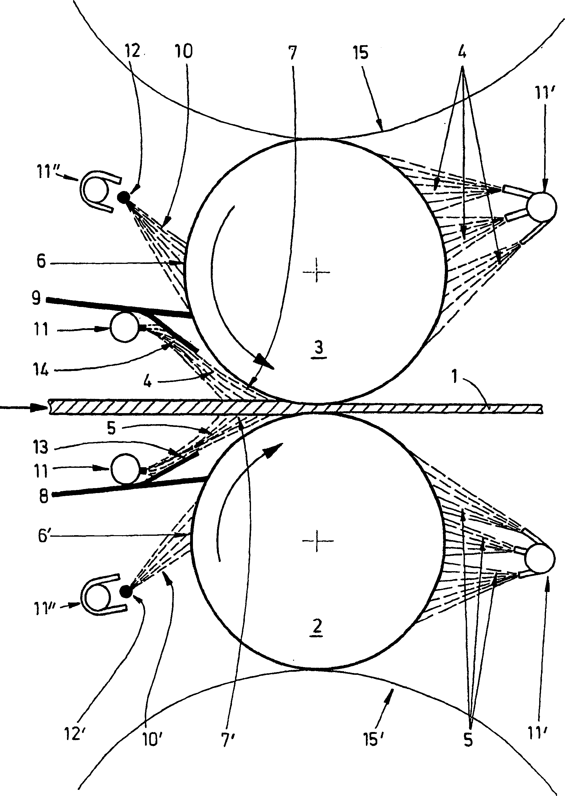
[0032] according to figure 1 , the thickness of a rolling strip 1 is reduced by approximately 50% in one pass between the work rolls 2, 3 of a rolling mill, not shown in detail. The subsequent rolling mill, also not shown in detail, has an approximately equally high pass reduction. In order to limit the high mechanical and thermal loads and to prevent deterioration of the roll surface in the event of an increasing number of rolled strips, the combined implementation of strip surface cooling and roll surface lubrication is carried out according to the following measures.

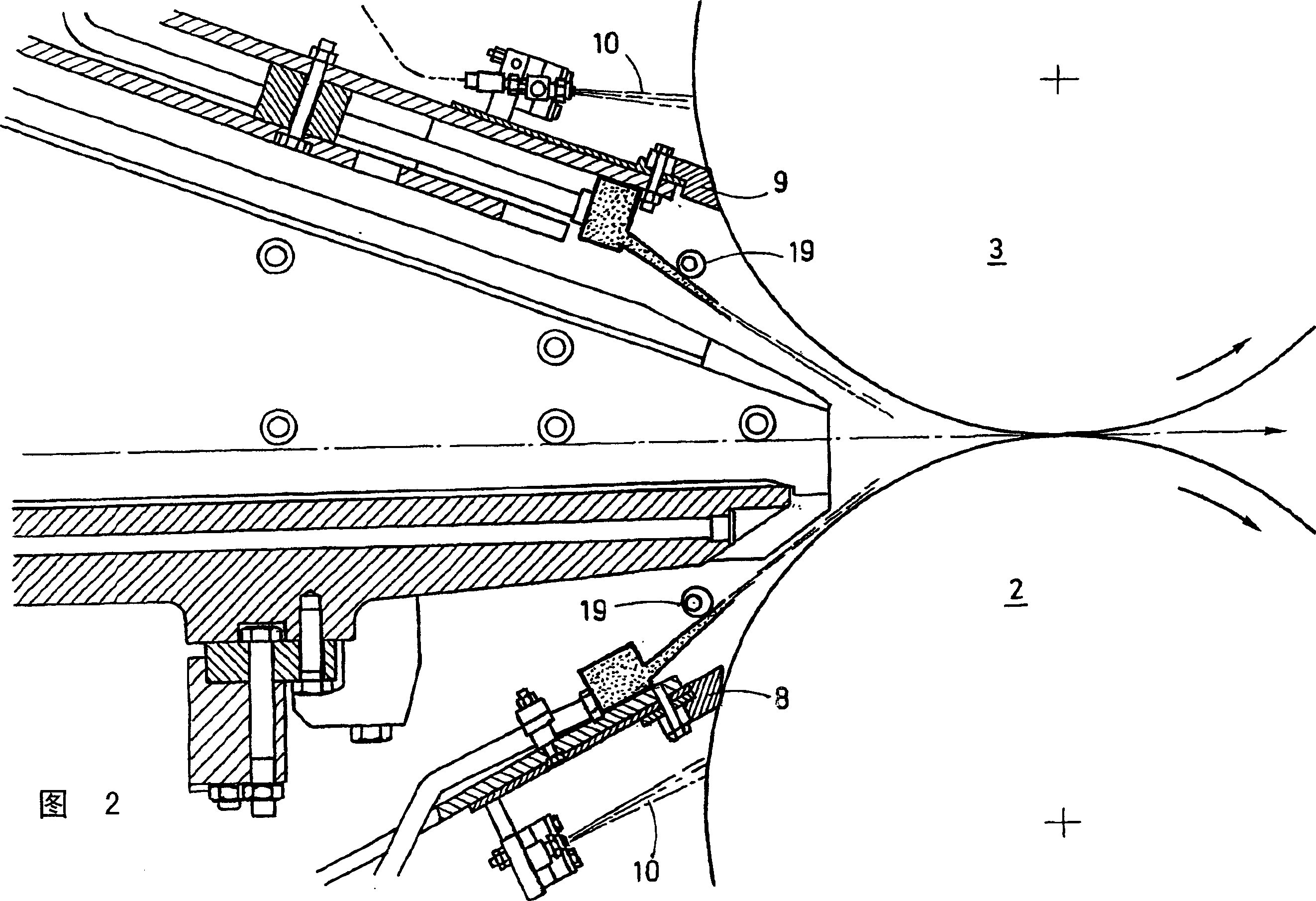
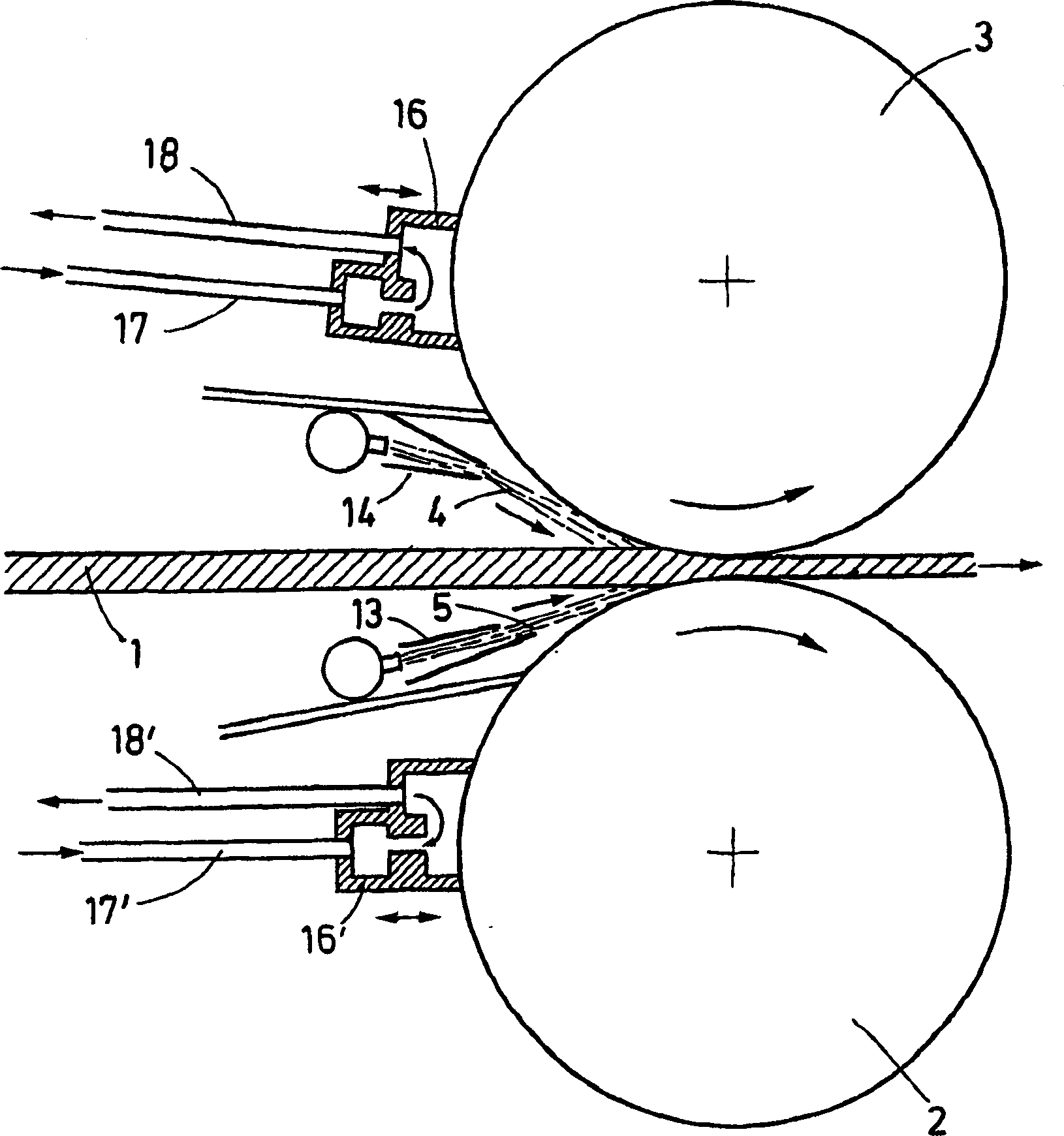
[0033]In the cooling lubricating device shown, the substances, ie water and lubricant, are supplied respectively, not shown in detail, to separate storage containers and separate feeds to the water 4 , 5 application means 11 , 11 ′; 11 ″ Pipelines and delivery lines leading to the lubricant 10, 10' application mechanism 12, 12'. Usually, these application mechanisms are designed in the shape of an oil inject...


PUM


Abstract

The invention relates to a method and a device for cooling and/or lubricating rollers, in particular the working rollers (2, 3) on a rolling stand and a rolled strip (1), rolled between the above rollers and transported onwards, using water in the form of spray jets (4, 5) as cooling medium and oil, oil/air mix, oil/water mix, oil/air/water mix or grease mixtures as lubricant. In order to improve the lubricating and cooling effects, a combined application of super-cooling the strip and roller surfaces and roller lubrication on the input side of the stand is disclosed, in which both media, water and lubricant, are separately fed to the rollers (2, 3) and the rolled strip and applied to the roller surface at different application points. Separate reservoirs for water and lubricant and separate lines to the spraying bar (11) for water and the spraying bar (12) for the lubricant are provided.

Description

technical field [0001] The invention relates to a method for cooling and / or lubricating rolls, in particular working rolls of a rolling mill, and a rolling strip which passes between the rolls during rolling. Background technique [0002] Especially when rolling thin slabs to small final thicknesses, large numbers of reductions are required in the individual rolling stands. In this case, very high roll loads and in particular mechanical and thermal loads on the work rolls occur. As a result, the roll surface deteriorates especially in the first few stands as the amount of strip being rolled increases. This manifests itself as a roughening of the roll, or even pitting, where the scale detaches locally from the roll. The uneven roll roughness that occurs in this case eventually leads to scale being rolled into the strip surface, whereby the strip surface quality also deteriorates. [0003] If the strip reduction is extremely high, work roll chatter, ie torsional vibration o...

Claims


Application Information

Patent Timeline
Patent Type & Authority Applications(China)
IPC IPC(8): B21B27/10B21B45/02
CPCB21B45/0233B21B45/0218B21B45/0251B21B27/10
Inventor J·赛德尔
Owner SMS DEMAG AG
Why Eureka
Try Eureka