Electrooptical composite connector, electrooptical composite cable and network appts.

A connector, electro-optical technology, applied in the field of devices, can solve the problems of optical fiber loss safety, signal loss, etc., and achieve the effect of signal loss suppression

Inactive Publication Date: 2004-10-27
SONY CORP
View PDF0 Cites 22 Cited by
  • Summary
  • Abstract
  • Description
  • Claims
  • Application Information

AI Technical Summary

Problems solved by technology

This will cause problems with possible signal loss if dust or dirt sticks to the fiber when the ferrule is inserted or removed
[0013] In addition, the use of optical fiber will include the possibility of loss due to cracks and safety issues due to the use of lasers

Method used


Image

  • Electrooptical composite connector, electrooptical composite cable and network appts.
  • Electrooptical composite connector, electrooptical composite cable and network appts.
  • Electrooptical composite connector, electrooptical composite cable and network appts.

Examples


Embodiment Construction

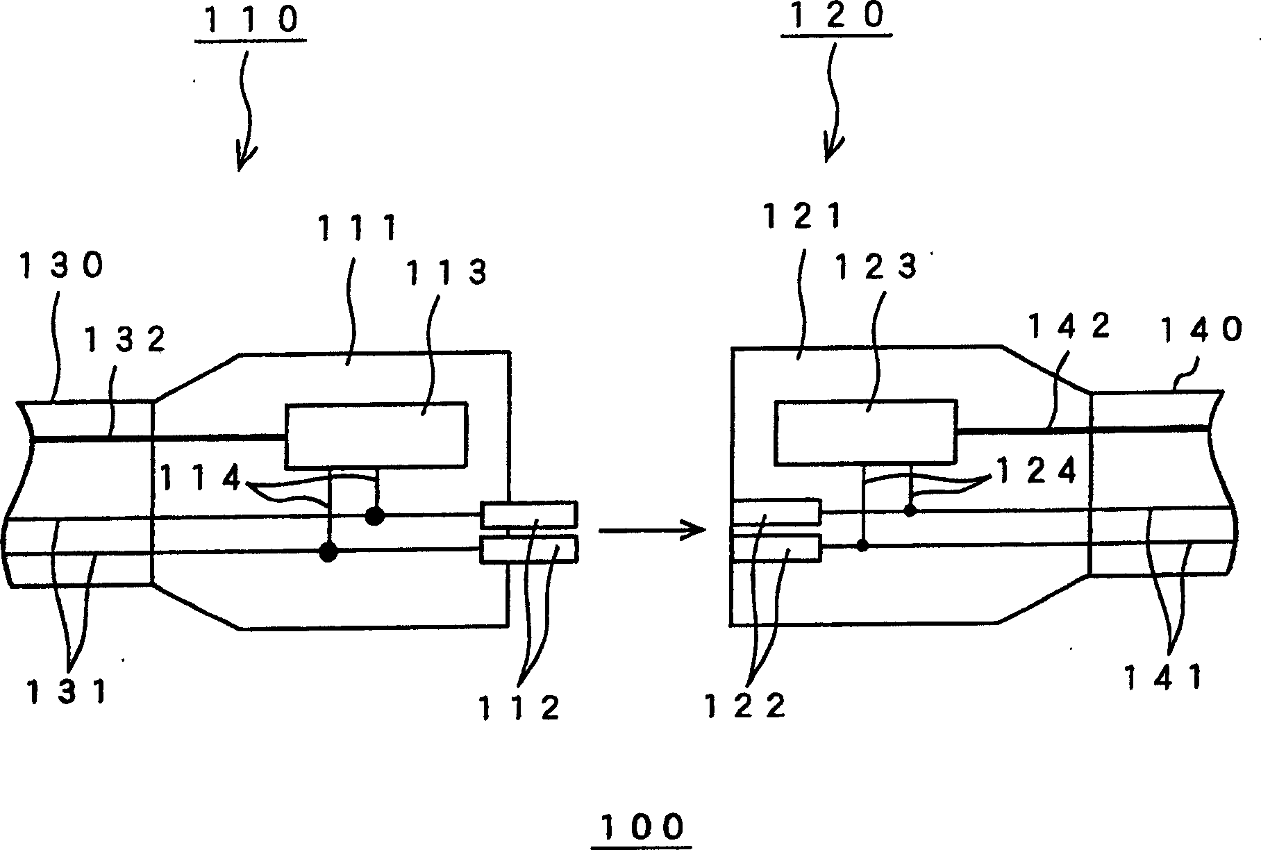
[0040] A first embodiment of the present invention will be described below with reference to the drawings. image 3 The structure of the electro-optical composite connector 100 according to the first embodiment of the present invention is shown.

[0041] Such as image 3 As shown, the electro-optic composite connector 100 includes an electro-optic composite plug 110 and an electro-optic composite socket 120 . exist image 3 In the state shown, the cable 130 is connected to the electro-optic composite plug 110 , and the cable 140 is connected to the electro-optic composite socket 120 . The cable 130 includes power lines 131 and optical fibers 132 . Cable 140 also includes power lines 141 and optical fibers 142 .

[0042] The electro-optical composite plug 110 includes a housing 111 , a power connection metal 112 , a transceiver 113 serving as a signal converting means, and lead wires 114 .

[0043] The structure of the housing 111 is basically the same as that of a general po...


PUM


Abstract

The electro-optical composite connector comprises an electro-optical composite plug and an electro-optical receptacle. The electro-optical composite plug or electro-optical composite receptacle converts an optical signal from an optical fiber to an electric signal and transmits to the opposing electro-optical receptacle or electro-optical composite plug through a power connecting metal or power connecting metal receiver. The opposing electro-optical composite receptacle or electro-optical composite plug converts the electric signal to the optical signal and transmits to the optical fiber.

Description

field of invention [0001] The present invention relates to a device including a power line, an information line, and the like for transmitting information between information communication devices. In particular, it relates to an electro-optic composite connector, an electro-optic composite cable, and a network device using the same. Background technique [0002] Conventionally, devices including power lines, information lines, and the like for transmitting information between information communication devices have been developed. Such devices have a complex configuration of wiring between communication devices. So far, radio communication, wire wiring, electro-optic composite cable, etc. have been proposed to solve the problem of complexity between information communication devices. [0003] However, radio communication has problems in information security due to its low directivity. In addition, it also has a problem of changing the communication speed depending on atmo...

Claims


Application Information

Patent Timeline
Patent Type & Authority Applications(China)
IPC IPC(8): G02B6/32G02B6/38G02B6/42H01R13/46H01R13/66H01R25/00
CPCH01R13/665G02B6/4201G02B6/4292G02B6/4246G02B6/4284A47G9/10A47G2009/1018
Inventor 长岛善哉兼平浩纪渡部义昭
Owner SONY CORP
Why Eureka
Try Eureka