Constitution method of heat exchange quantity analogue program and storage medium of sotraging such program

A technology for simulating programs and heat exchange, applied in the field of simulation programs, and can solve problems such as complex programs

Inactive Publication Date: 2004-10-27
FUJITSU GENERAL LTD
View PDF2 Cites 3 Cited by
  • Summary
  • Abstract
  • Description
  • Claims
  • Application Information

AI Technical Summary

Problems solved by technology

In addition, in the existing program, an algorithm using a conditional branch is used using a flag for selecting an equivalent expression. It is...

Method used


Image

  • Constitution method of heat exchange quantity analogue program and storage medium of sotraging such program
  • Constitution method of heat exchange quantity analogue program and storage medium of sotraging such program
  • Constitution method of heat exchange quantity analogue program and storage medium of sotraging such program

Examples


Embodiment 1

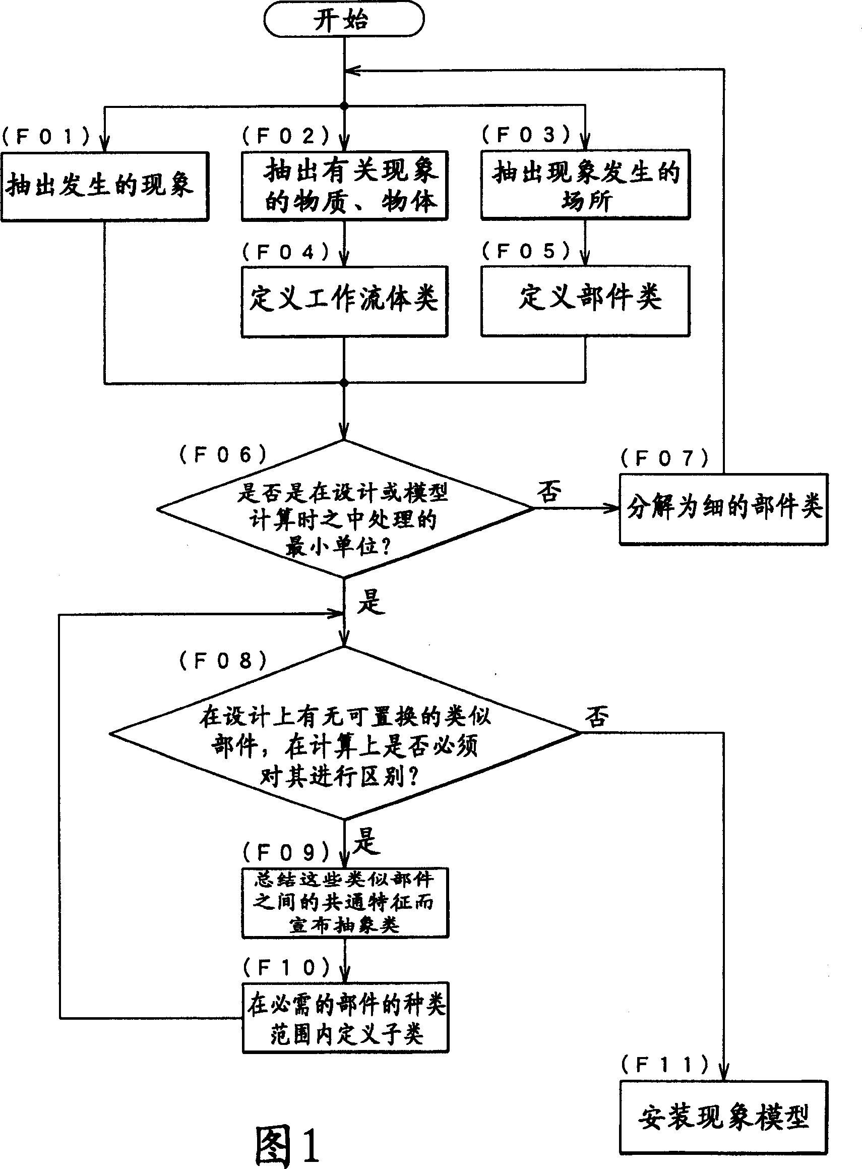
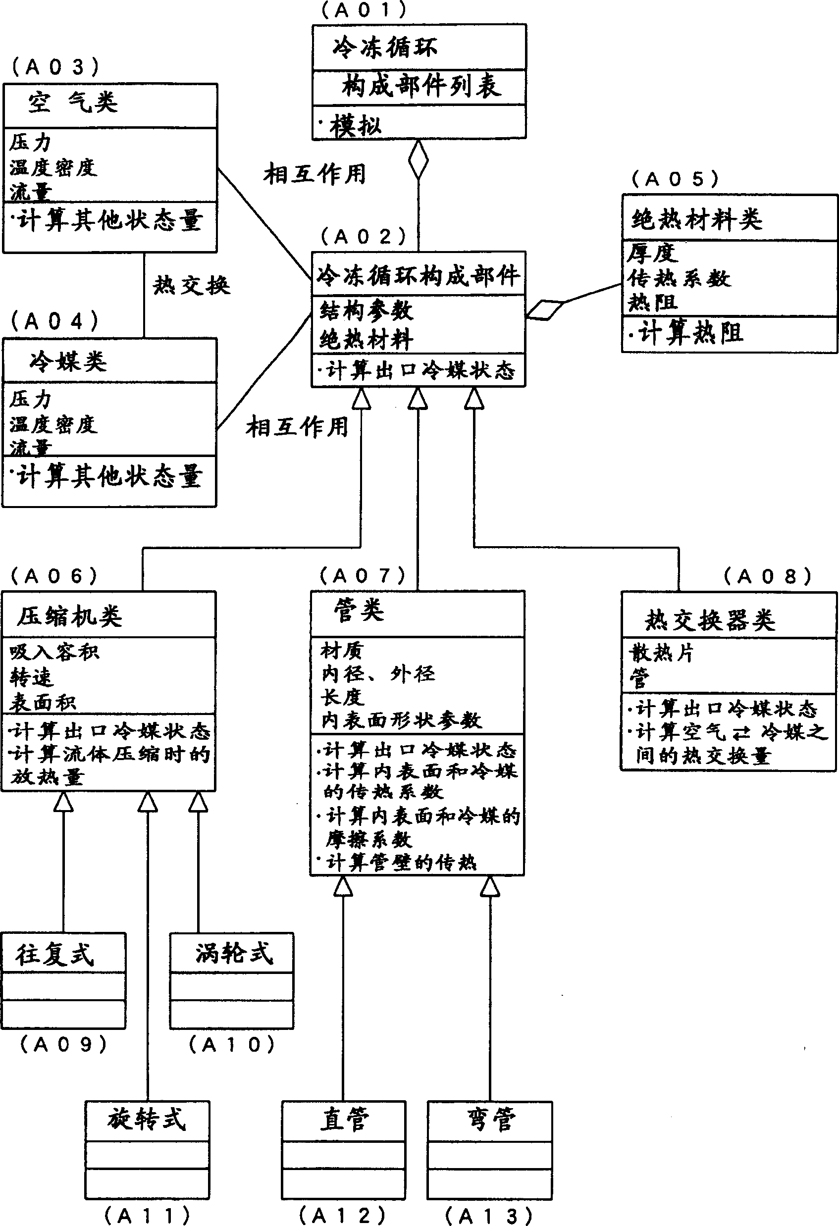
[0022] The so-called refrigeration cycle is a device that is composed of a compressor, a heat exchanger, a heat insulating material, etc. to obtain a refrigeration effect, and is used below figure 2 A case where the simulation method of the present invention is applied to generate a program for simulating the heat exchange amounts of air and refrigerant as all these components will be described. First, the refrigerating cycle (A01) is composed of refrigerating cycle components (A02). Air (A03) and refrigerant (A04) are defined as working fluids interacting with this refrigeration cycle constituent component (A02). In addition, considering the case where the components are covered with heat insulating materials, the configuration of the refrigerating cycle components (A02) also concentrates on the heat insulating materials (A05). These are classes defined by the flow of (F01) to (F05) in the flowchart of FIG. 1 .

[0023] Here, if it is judged whether the refrigerating cycle ...

Embodiment 2

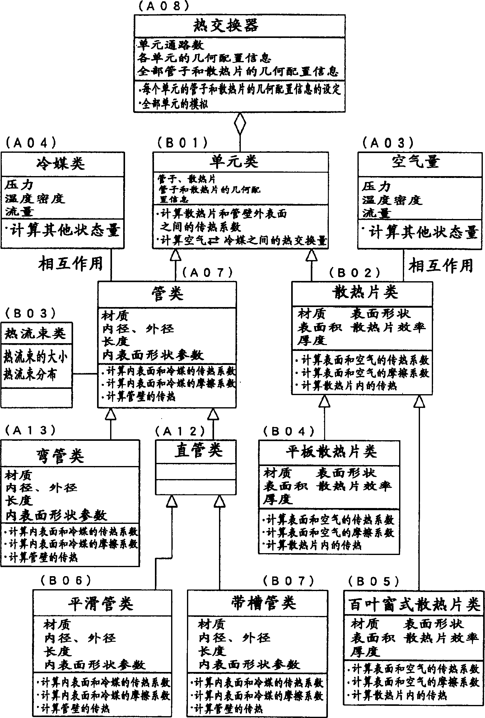
[0029] Use below image 3 The configuration method of the heat exchanger will be described. In Embodiment 1 above, the refrigeration cycle is divided into each component to consider the heat exchange amount, but in the case of the heat exchanger, the heat exchanger is divided into small parts called units, and the heat exchange rate of each unit is calculated. Finally, the heat exchange amount of the whole heat exchanger is obtained by accumulating the heat exchange amount of all units. The size of the division unit is set so small that there is no problem in expressing the state change of the working fluid occurring therein even with one expression.

[0030] To reflect this division into units in the class definition, as in image 3 As shown, the heat exchange class (A08) is composed of unit classes (B01). In addition, the geometric configuration information of the unit, the number of channels, the geometric configuration information of the overall tubes and fins, etc. are...


PUM


Abstract

The present invention provides a simulation method for an apparatus which produces refrigeration effect by means of heat exchange between refrigerant and air, wherein the simulation method provides good expandability to allow new parts to be added and so on. The method includes the steps of: classifying models which represent phenomena occurring in various components of an apparatus for producing refrigeration effect by means of heat exchange between refrigerant and air into categories independent of one another; defining the resulting categories as classes; defining an abstract class by extracting characteristics common to a plurality of similar parts contained in each category if these parts need to be distinguished for the purpose of calculation; providing, under the abstract class, as many subclasses which inherit character of the abstract class as there are necessary types of part; implementing a phenomenological model of each defined class; and creating a simulation program in an object-oriented language based on the classes.

Description

technical field [0001] The present invention relates to a simulation program for simulating the heat exchange amount of a device for obtaining a refrigeration effect by heat exchange between a refrigerant (refrigerant) and air, and to a class definition method for constructing the program using an object-oriented language. Background technique [0002] As a device for obtaining the refrigeration effect by heat exchange between the refrigerant and the air, for example, a refrigeration cycle and a heat exchanger (heat exchanger) as a part of the refrigeration cycle can be mentioned. When designing these devices, simulation is currently used. The program predicts in advance the heat exchange capacity of the device. If the heat exchange amount of such a device can be predicted with high accuracy, the performance of the designed device can be predicted, and a device meeting the required performance can be designed. As a simulation method of a refrigerant circuit, there is Patent...

Claims


Application Information

Patent Timeline
IPC IPC(8): F25B1/00F25B39/00G06F9/44G06F9/45G06F9/455G06F17/50G06F19/00
CPCG06F17/5018G06F2217/34G06F30/23G06F2113/14H02G3/121H02G3/081H02G3/083H02G3/36
Inventor 笹野雅惠楠本伸广稲垣雄史
Owner FUJITSU GENERAL LTD
Why Eureka
Try Eureka