
Technique for laser cutting metal tube utilizing compressed air and apparatus thereof

A compressed air and laser cutting technology, which is applied in the field of laser applications, can solve the problems of focusing lens deformation, increased manufacturing cost, and high cost, and achieve the effects of preventing local overheating, saving oxygen consumption, and reducing temperature

Inactive Publication Date: 2004-11-03
CHANGCHUN INST OF OPTICS FINE MECHANICS & PHYSICS CHINESE ACAD OF SCI
View PDF0 Cites 15 Cited by
  • Summary
  • Abstract
  • Description
  • Claims
  • Application Information

AI Technical Summary

Problems solved by technology

However, this process method consumes 4-5 times the amount of oxygen consumed by the usual cutting plate, which is expensive, and because it works under high pressure conditions, the focusing lens is prone to deformation or even damage, so the design must take into account the relevant Protective measures also increase the corresponding manufacturing costs, etc.

Method used


Image

  • Technique for laser cutting metal tube utilizing compressed air and apparatus thereof
  • Technique for laser cutting metal tube utilizing compressed air and apparatus thereof

Examples


Embodiment Construction

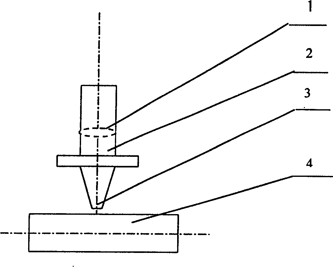
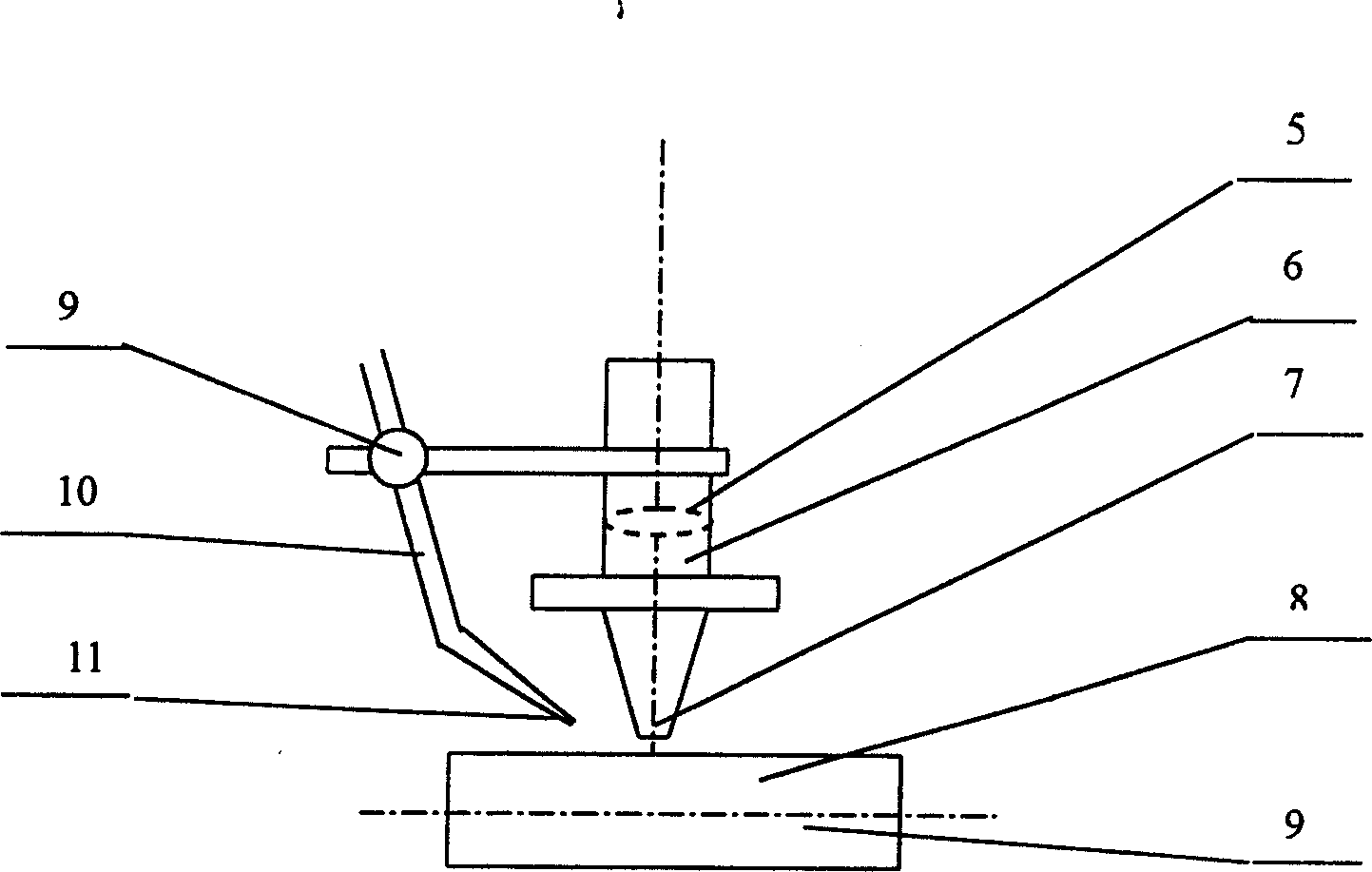
[0010] The invention consists of figure 2 The shown laser cutting head device implements the process of introducing compressed air into the laser cutting metal pipe. The oxygen pressure used is 0.18MPa, and the angle between the compressed air nozzle 11 and the oxygen nozzle 7 is 45°. The air pressure is 0.35MPa, the distance between the compressed air nozzle 11 and the oxygen nozzle 7 is 20mm, and the distance between the compressed air nozzle 11 and the workpiece 8 to be cut is 8mm.

[0011] figure 2 As shown in the laser cutting head device, the laser adopts CO2 axial flow laser, the material of compressed air nozzle 10 and nozzle 11 is made of pure copper, the inner diameter of nozzle 10 is Φ8mm, the outer diameter is Φ10mm, and the outlet diameter of nozzle 11 is Φ3 .2mm, the nozzle 10 and the nozzle 11 are connected by brazing, the direction of the compressed air nozzle 11 forms an angle of 45° with the oxygen nozzle 7, the distance between the compressed air nozzle 1...


PUM


Abstract

The present invention belongs to the field of laser cutting apparatus and the technological scheme is that the laser cutting apparatus consists of focus lens, cutting laser head, oxygen nozzle, nozzle regulating support and compressed air nozzle. One regulating support is installed for the cutting laser head to regulate the angle between the compressed air nozzle and the oxygen nozzle within 40-50 deg, the distance between the compressed air nozzle and the oxygen nozzle within 15-25 mm, the distance between the compressed air nozzle and the cut workpiece within 6-10 mm and pressure of compressed air in 1.5-2.5 times that of oxygen. The method and apparatus of the present invention can avoid overheat during cutting process.

Description

1. Technical field [0001] The invention belongs to the technical field of laser application and relates to a process method of using compressed air for laser cutting metal pipes and a laser cutting head device thereof. 2. Technical background [0002] When laser cutting metal pipes, there will be some phenomena different from those of flat metal sheet workpieces. Due to the structural characteristics of metal pipes, during laser cutting, the generated metal slag will inevitably be sprayed on the other side of the pipe incision. On the inner surface of one side, the local temperature of the pipe workpiece rises rapidly, especially for pipes with small diameters, the thermal effect is more obvious, which can directly lead to the decline of laser cutting quality, or even the inability to continue cutting. Therefore, how to solve the problem of local overheating of metal pipes during laser cutting is a problem that must be considered to improve the quality of laser cutting. [...

Claims


Application Information

Patent Timeline
Patent Type & Authority Applications(China)
IPC IPC(8): B23K26/14
Inventor 谢冀江
Owner CHANGCHUN INST OF OPTICS FINE MECHANICS & PHYSICS CHINESE ACAD OF SCI
Learn More