Catalyst or sorbent beds

A fixed bed and element technology, applied in solid adsorbent liquid separation, cyanide, inorganic chemistry, etc., can solve the problem of reducing the contact time between fluid and catalyst or adsorbent, and achieve the effect of reducing the possibility

Inactive Publication Date: 2004-11-10
JOHNSON MATTHEY PLC
View PDF1 Cites 7 Cited by
  • Summary
  • Abstract
  • Description
  • Claims
  • Application Information

AI Technical Summary

Problems solved by technology

[0006] Increased flow through the bed reduces contact time between f

Method used


Image

  • Catalyst or sorbent beds
  • Catalyst or sorbent beds
  • Catalyst or sorbent beds

Examples


Embodiment Construction

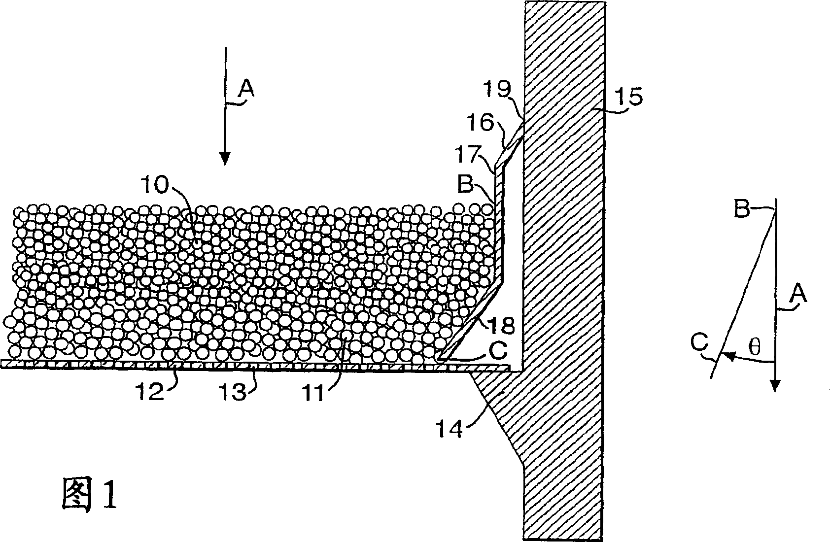
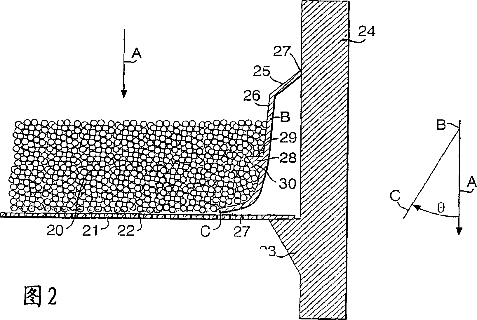
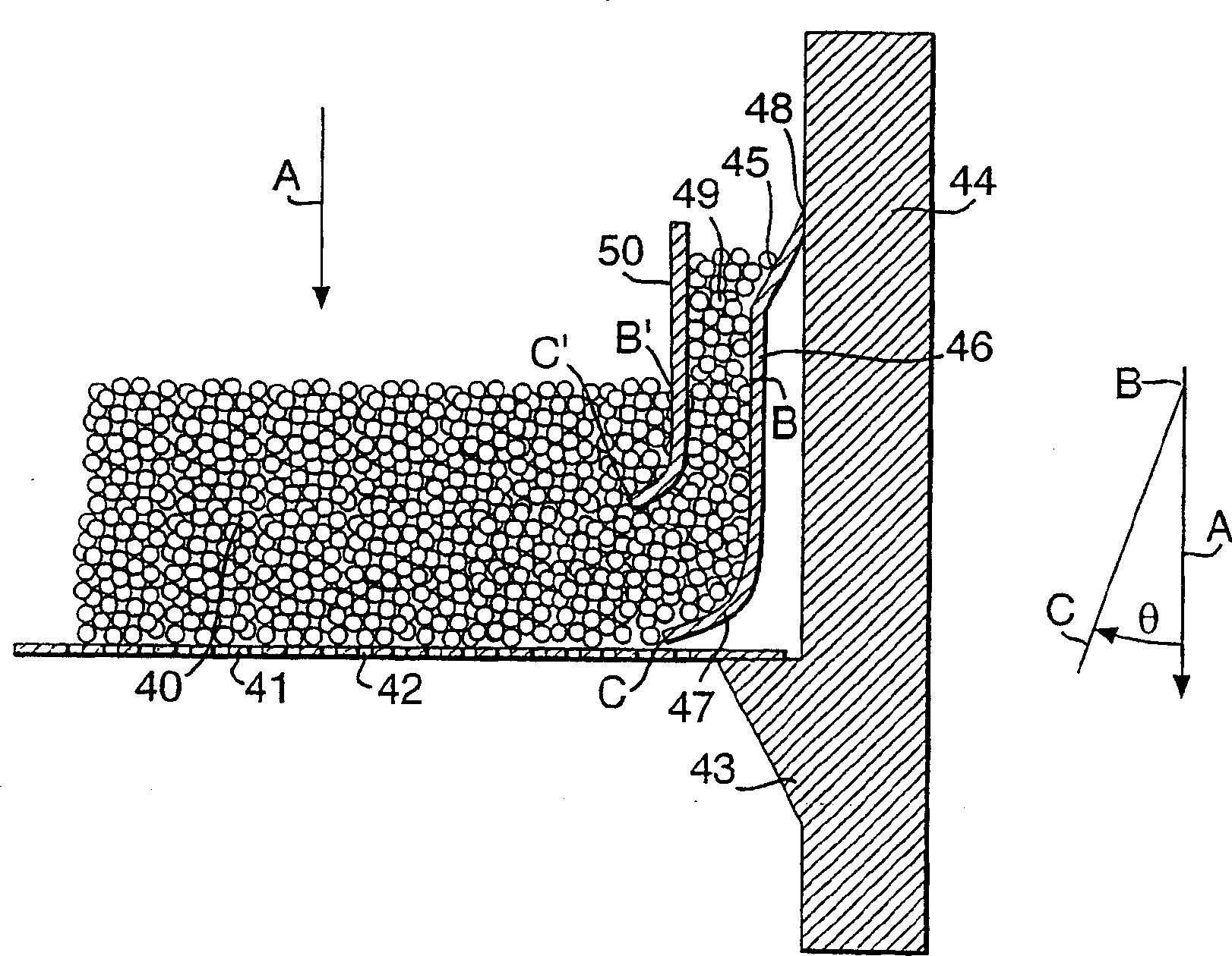
[0030] In Figures 1, 2 and 3, the direction of treatment fluid flow through the majority of the bed is indicated by arrow "A", which direction is substantially vertical. For clarity, Figures 1, 2, and 3 show the direction of treatment fluid flow through the majority of the bed (A) and the line drawn between the lower end of the boundary element (C) and the surface of the bed (B). The total angle (θ) of .

[0031] Referring to the drawings, Figure 1 shows a catalyst bed for example for ammoxidation. The bed is provided by a layer of cobalt-containing catalyst particles 10 on a layer of relatively large size inert alumina particles 11 disposed on a perforated element 12 having holes 13 enabling gas to flow through the bed. The bed is supported by perforated elements 12 which rest against lugs 14 connected to the container wall 15 .

[0032] The boundary elements include straight facets 16 , 17 and 18 that prevent the bed 10 from contacting the vessel wall 15 . The facet 16 is...


PUM


Abstract

A fixed bed containing a particulate catalyst or sorbent material (10) subject to operation at high temperature having a shaped boundary member (16) inclined to the direction of fluid flow through the bed that maintains the depth of said catalyst or sorbent at the boundary of the bed through a series of thermal expansion-thermal contraction cycles is described. By maintaining bed depth, the shaped boundary member (16) can prevent bypass of, e.g. ammonia through a bed of particulate ammonia oxidation catalyst.

Description

technical field [0001] The present invention relates to a fixed bed of catalyst or adsorbent, in particular to a device for increasing the efficiency of the bed by maintaining the thickness of the bed through a series of thermal expansion-thermal contraction cycles. Background technique [0002] A fixed bed generally comprises at least one layer of catalyst or adsorbent in the form of granular material in the form of extrudates, pellets or pellets bounded by process fluid-impermeable boundary elements and arranged in a perforated On elements, such as perforated plates, grids or meshes, treatment fluid passing through the bed can pass through said perforated elements. The bed is disposed within a vessel wherein the bed is supported directly by the vessel wall, eg by lugs, or by process fluid impermeable bed support means such as a basket or frame attached to the vessel wall. [0003] The boundary elements may or may not be fixed to the perforated element. However, the bound...

Claims


Application Information

Patent Timeline
IPC IPC(8): B01D15/00B01D53/04B01D53/18B01J8/00B01J8/02C01B3/38C01B21/26C01C3/02C07C45/38C10G25/00C10G49/00
CPCC01B2203/1258B01D2259/414B01J2208/00884B01J2208/025C07C45/38B01J2208/0084C01B2203/127C10G25/00B01D2257/602C01C3/0216B01J8/008B01D53/0423C01B3/386C01B2203/1011B01D2257/55B01J8/025B01D2257/2045C01B21/265B01D2257/30C10G49/002C01C3/0225C01B2203/0261B01J2219/1923Y02P20/52C07C47/04B01J8/02
Inventor 肖恩·A·阿克索阿兰·B·布里斯通安德鲁·M·沃德
Owner JOHNSON MATTHEY PLC
Why Eureka
Try Eureka