Luminous container

A technology for light-emitting devices and containers, which can be applied to containers, rigid containers, drinking vessels, etc., can solve the problem that light-emitting devices cannot be sealed, and achieve the effects of light weight, long service life and simple structure

Inactive Publication Date: 2004-11-17
ZHEJIANG UNIV
View PDF0 Cites 4 Cited by
  • Summary
  • Abstract
  • Description
  • Claims
  • Application Information

AI Technical Summary

Problems solved by technology

Since the battery cannot be used for a long time and needs to be replaced frequently, the light-emitting device of the cup cannot be sealed, and the liquid in the cup will inevitably flow into the light-emitting device and damage the circuit, resulting in failure of the light-emitting device

Method used


Image

  • Luminous container
  • Luminous container
  • Luminous container

Examples


Embodiment Construction

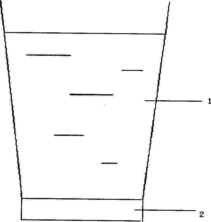
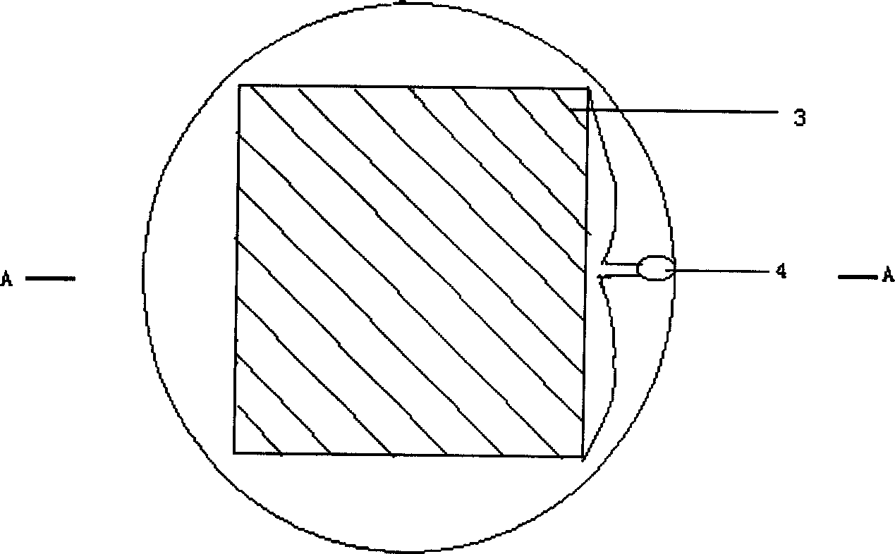
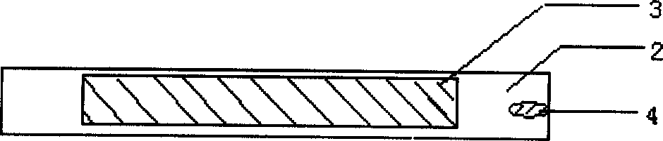
[0011] refer to figure 1 , the light-emitting container of the present invention includes a container 1 and a sealed light-emitting device 2. In the specific example shown in the figure, the sealed light-emitting device 2 is fixed on the bottom of the container 1, and the light-emitting device can be as figure 2 As shown, there is a thermoelectric conversion device 3 and a light emitting device 4, here, the thermoelectric conversion device 3 is P-type and N-type Bi 2 Te 3 The base thermoelectric material board, the light emitting device 4 is a light emitting diode, and the light emitting diode is connected with P-type and N-type Bi 2 Te 3 The electrodes of the base thermoelectric material plate are connected.

[0012] In the light-emitting container of the present invention, the sealed light-emitting device 2 can also be made into a ring shape, and the container 1 is placed in the light-emitting device 2 so as to be in close contact with the light-emitting device 2 .


PUM


Abstract

The invention provides a luminous container for realizing luminescent function by means of thermoelectric materials, wherein a sealed luminescent device is arranged on the outer surface of the container, the luminescent device includes a thermoelectric converter and a luminescent unit, the electrodes of the luminescent device is connected with the luminescent unit, thus forming a current loop.

Description

technical field [0001] The invention relates to a container capable of emitting light without a power source. Background technique [0002] Present containers, including cups, bowls, bottles, etc. of various qualities, are monotonous in variety, mostly only pay attention to their practicality and ignore ornamental and interesting properties, and do not have luminous function. Although there are light-emitting cups abroad, they need to be powered by batteries. Because the battery cannot be used for a long time and needs to be replaced frequently, the light-emitting device of the cup cannot be sealed, and the liquid in the cup will inevitably flow into the light-emitting device to damage the circuit and cause the light-emitting device to fail. Contents of the invention [0003] The purpose of the present invention is to provide a light-emitting container with light-emitting function to beautify human life. [0004] The te...

Claims


Application Information

Patent Timeline
Patent Type & Authority Applications(China)
IPC IPC(8): A47G19/00A47G19/22B65D1/00H01L35/16H01L35/18
Inventor 赵新兵殷浩倪华良邬剑波
Owner ZHEJIANG UNIV
Why Eureka
Try Eureka