Infrared heat wave detecting system with THZ wave as light source

A detection system, infrared heat wave technology, used in measurement devices, material defect testing, material analysis by optical means, etc.

Inactive Publication Date: 2004-11-24
CAPITAL NORMAL UNIVERSITY +1
View PDF3 Cites 17 Cited by
  • Summary
  • Abstract
  • Description
  • Claims
  • Application Information

AI Technical Summary

Problems solved by technology

More importantly, the existing measurement technology can simultaneously obtain the amplitude and phase of each frequency component covered by its bandwidth without post-processing with the help of the Kramers-Kronig relationship, which cannot be achieved by ordinary optical technology

Method used


Image

  • Infrared heat wave detecting system with THZ wave as light source
  • Infrared heat wave detecting system with THZ wave as light source

Examples


Embodiment Construction

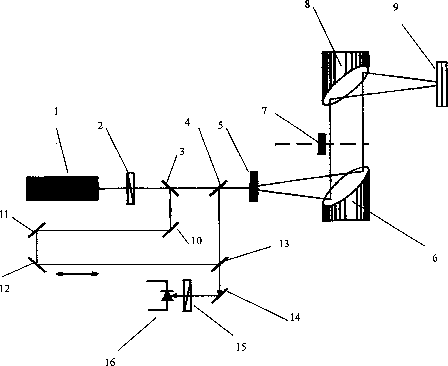
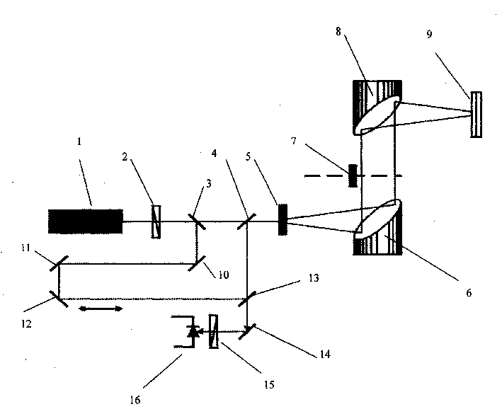
[0022] refer to figure 1 , this infrared thermal wave detection system integrates the THz wave generation system, the THz wave heating system and the THz wave imaging system. A beam of pulsed light source is emitted by the laser 1 with a wavelength of 800nm ​​and a pulse width of 30fs, which passes through the polarizer 2. Divide the light beam into two beams through the beam splitter 3, and one beam of pump light passes through the beam splitter 3 and the beam splitter 4 and irradiates the crystal 5, and generates a pulsed THz wave, which passes through the paraboloid Mirror 6, chopper 7, and parabolic mirror 8 irradiate the sample 9, and then the THz wave reflected on the sample 9 returns to the crystal 5 through the parabolic mirror 8, chopper 7, and parabolic mirror 6 according to the original path. And through the crystal 5, the crystal 5 is a ZnTe electro-optic crystal. Another beam of probe light reflected by the beam splitter 3 passes through a delayed optical path co...


PUM

PropertyMeasurementUnit
wavelengthaaaaaaaaaa
widthaaaaaaaaaa
widthaaaaaaaaaa

Abstract

The present invention relates to one new kind of thermal wave detecting system. It adopts THz wave as heat source for heating object; thermal imaging instrument to monitor the varying temperature field in the surface of the sample and detect the phase relation between the variance in the temperature field and the heat source applies the THz wave; synchronous or time sequence controller to control the emission of the THz wave and the detection of thermal imaging instrument; and computer for thermal wave transmission calculating processing and data fitting, so as to obtain the inner fault and heterogeneity information from the temperature field variation.

Description

technical field [0001] The invention relates to the technical field of non-destructive flaw detection, in particular to a method and an instrument for infrared thermal wave detection. Background technique [0002] Infrared thermal wave non-destructive flaw detection technology has been reported in many literatures. It uses a special mode of thermal excitation, adopts modern infrared imaging technology, and performs time-series thermal wave signal detection and data acquisition under computer control. The special computer software developed with the modern image processing theoretical model performs real-time image signal processing and analysis, and obtains the digital tomogram inside the object, so that the three-dimensional visual quantitative diagnosis of the internal defect or damage of the object can be carried out on the engineering site and in the field. [0003] Infrared thermal wave non-destructive testing technology has a wide range of applications, such as: safety...

Claims


Application Information

Patent Timeline
Patent Type & Authority Applications(China)
IPC IPC(8): G01N21/17G01N25/72
Inventor 张存林金万平
Owner CAPITAL NORMAL UNIVERSITY
Why Eureka
Try Eureka