Method and System for Automatic Defect Detection of Articles in Visual Inspection Machines

Inactive Publication Date: 2008-11-13
CAMTEK LTD
View PDF11 Cites 19 Cited by
  • Summary
  • Abstract
  • Description
  • Claims
  • Application Information

AI Technical Summary

Benefits of technology

[0016]A method and system is therefore proposed wherein the relation between a large set of processing, recognition, decision and reporting parameters, are to be optimized in parallel at short setup time automatically, and at constraints that are dictated before, during or after the inspection process. The optimization process proposed is based on a mathematical or cost function minimization scheme, which uses logical or heuristic or learned p

Problems solved by technology

As long as critical defects are repeatedly generated at the same location, this approach is acceptable, however, if a random or new local defect appears, the process of evaluating the criticality of the defect should start again, forming an unacceptable delay between defect generation to the automatic detection.
Accurate distinction between critical defects and non-critical defects, however, is not simple and in order to accurately classify critical defects, samples are used for training the system.
Preparing accurate critical defect samples for different types of defects generated in the production process through manual observation and classification, is difficult.
Additionally, defects that should be reported in a fine product may present an acceptable quality in a courser product of the same customer.
Drawbacks of the above-described third approach, include the requirement to verify position information by functional test results and the difficulty of setting up the classification rule in products other than semiconductor devices, where a wider image differentiation exists, as mentioned above with relation to the second approach.
Another drawback relates

Method used


Image

  • Method and System for Automatic Defect Detection of Articles in Visual Inspection Machines
  • Method and System for Automatic Defect Detection of Articles in Visual Inspection Machines
  • Method and System for Automatic Defect Detection of Articles in Visual Inspection Machines

Examples


Embodiment Construction

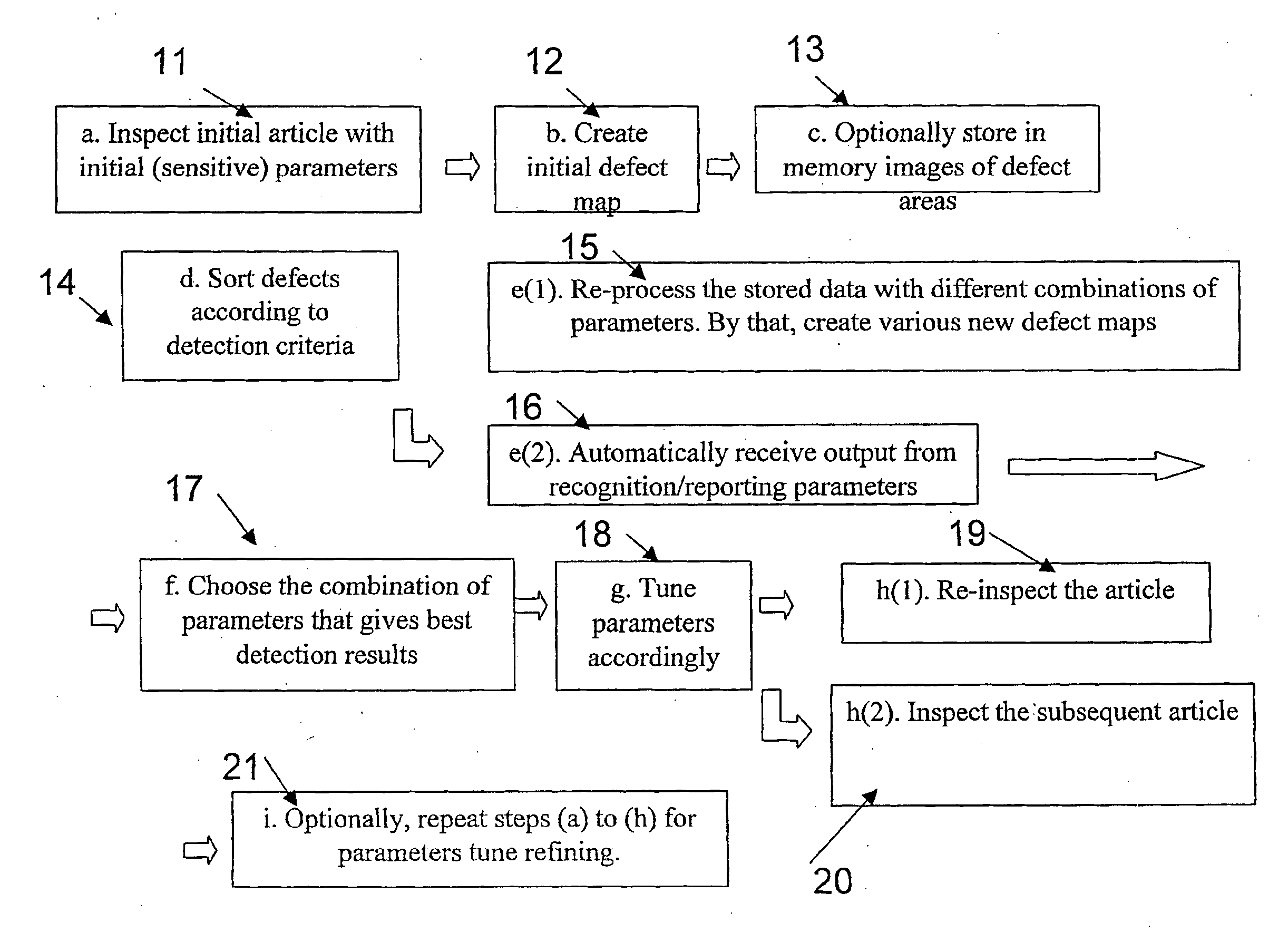
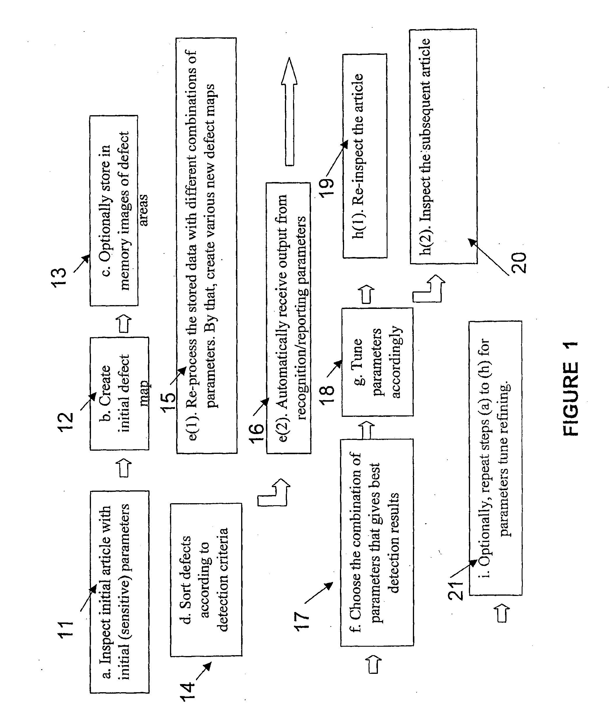
[0032]With reference to the drawings, FIG. 1 illustrates a flow diagram presenting a method for semi-automatic tuning of detection parameters in an automatic visual inspection system. The method is regarded as semi-automatic, as the decision of whether a defect received in the initial defect map is critical or non-critical, is performed manually by the user, preferably an experienced user such as the article's designer or automatically by the system. The flow between process steps is automatically sequenced by a controller.

[0033]In step (a) of block 11, the article, whether the first article in the batch or not, is inspected by scanning with an automatic optical inspection (AOI) system, using initial parameters. These initial parameters may be received either automatically, from initial setup or from default values within the system, or manually chosen from a parameter database. Preferably, a sensitive set of parameters is selected, such that it will result in detection of all criti...


PUM


Abstract

There is provided a method for establishing a parameters setup for inspecting a plurality of articles by an automatic inspection system. The method includes inspecting a first article by the inspection system, applying an automatic defects detection method according to a given set of inspection parameters, receiving an initial map of defects and sorting uncovered defects into defect types according to a predetermined set of defect types. While sorting defects, if new defects not recognized by the inspection system are detected, adding the new defects to the initial map to be sorted and automatically setting the inspection parameters by means of applying computational dedicated algorithms, using a heuristic approach, to form a modified parameters setup. The modified parameters setup is then used for obtaining a modified map of detected defects, and the modified parameters setup for inspecting other of the plurality of articles. A system for establishing a parameters setup for inspecting a plurality of articles is also provided.

Description

FIELD OF THE INVENTION[0001]The present invention relates to methods implemented in automatic visual inspection systems performed at intermediate process steps during repeated production of articles, and more particularly to methods for performing setup of inspection parameters in detecting defects by automatic inspection machines.BACKGROUND OF THE INVENTION[0002]During production of articles involved with multiple sequential process steps, such as printed circuits, semiconductor devices, or complex mechanical elements, there is a need for inspection, verification, and quality control steps between the process steps. The intermediate verification is required, in order to detect faulty articles and avoid performing ineffective, expensive process steps over articles, possibly critically defected during one of the early process steps. In some cases, functional tests of the article may only be performed after completion of the entire production process. For this reason, intermediate vis...

Claims


Application Information

Patent Timeline
IPC IPC(8): G06F19/00
CPCG06T7/001G06T2207/30148G06T2207/30164
Inventor ALGRANATI, DORANTROPP, ORENKAGAN, ROMAN
Owner CAMTEK LTD
Why Eureka
Try Eureka