Supercharge Your Innovation With Domain-Expert AI Agents!

Flat brushless motor

A brushless motor, flat technology, applied in the field of micro motors, can solve the problems of short life and high manufacturing cost, and achieve the effects of low manufacturing cost, high welding temperature and easy heat dissipation

Inactive Publication Date: 2004-11-24
乐清市陆宇微电机有限公司
View PDF0 Cites 0 Cited by
  • Summary
  • Abstract
  • Description
  • Claims
  • Application Information

AI Technical Summary

Problems solved by technology

[0006] (a) All designs have short life due to mechanically reversing structures;
[0007] (b) All designs require high precision and special alloys for mechanical reversing structures, resulting in high manufacturing costs;

Method used


Image

  • Flat brushless motor
  • Flat brushless motor
  • Flat brushless motor

Examples


Embodiment Construction

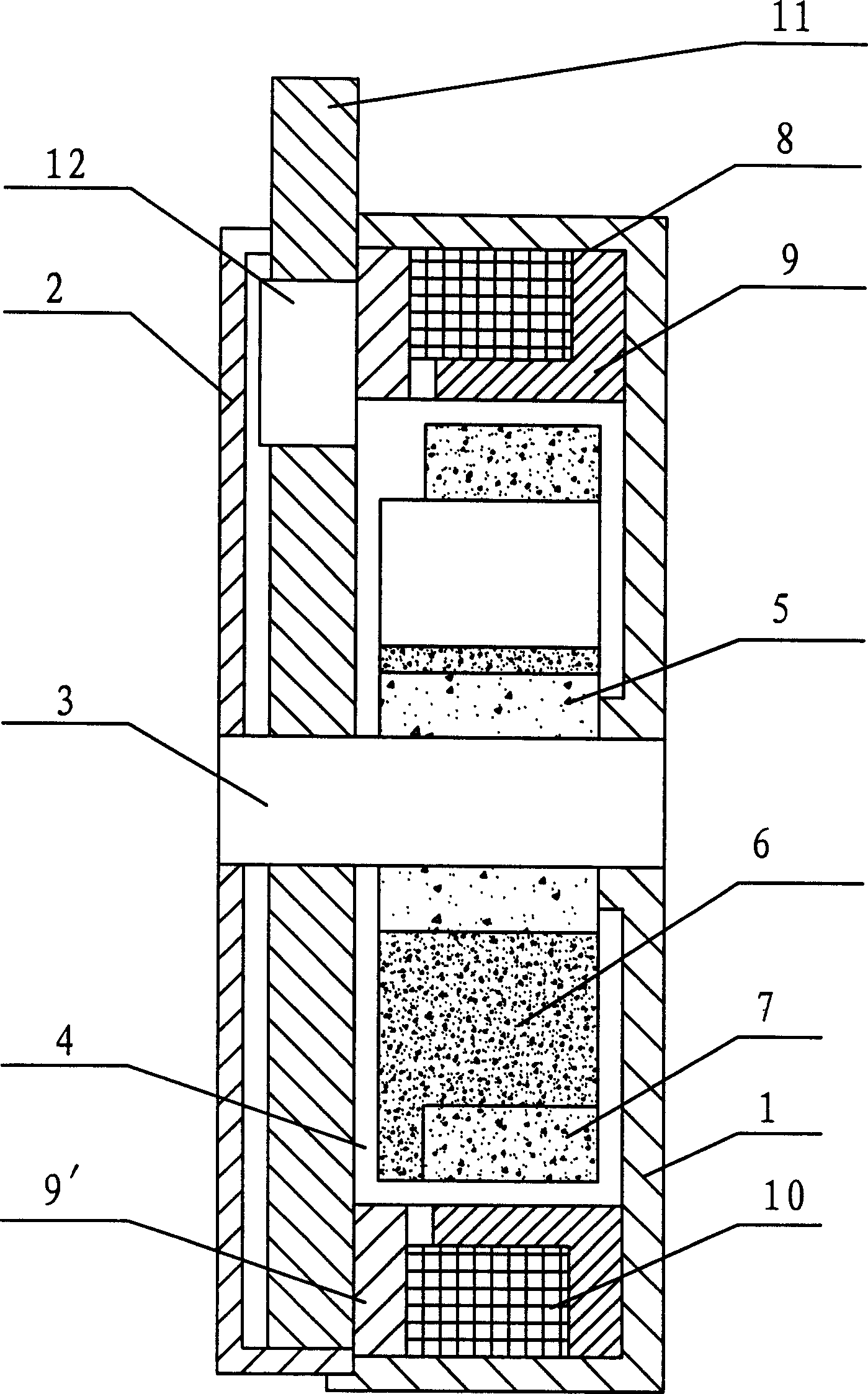
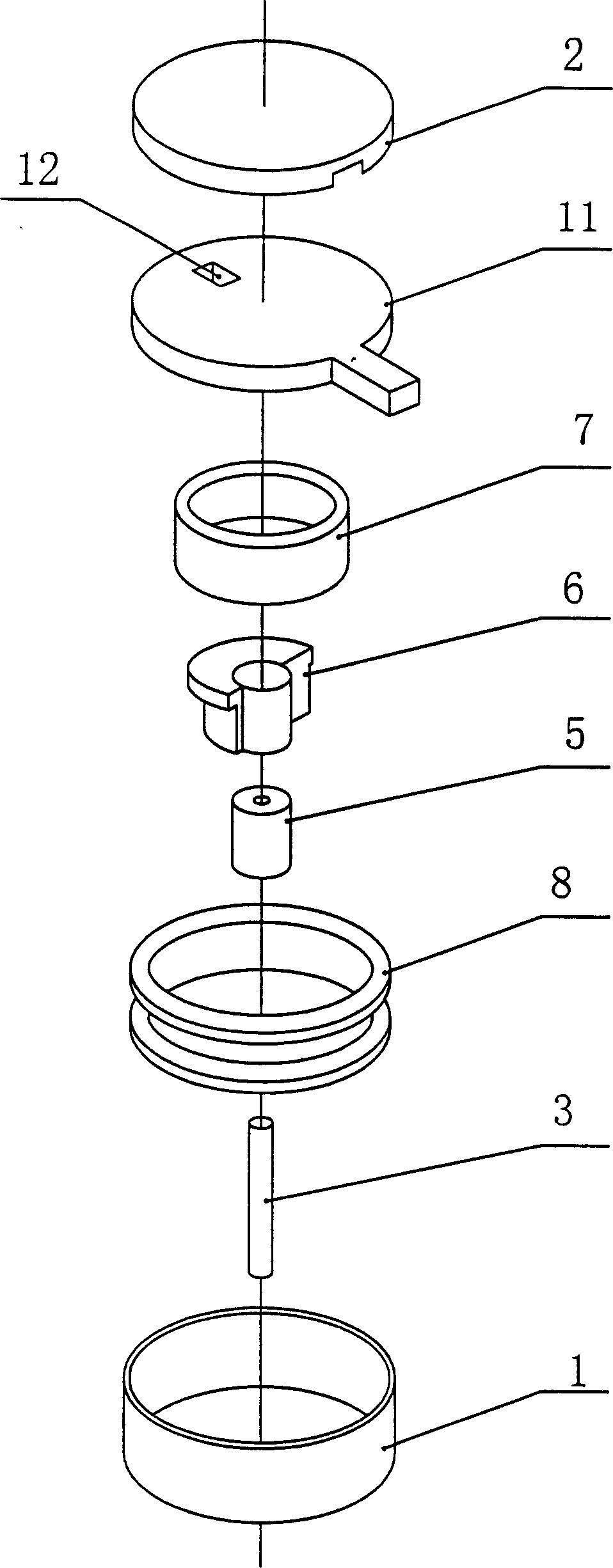
[0024] see figure 1 with figure 2 , The flat brushless motor of the present invention includes a cup-shaped base 1 , a cover 2 , a PCB printed circuit board 11 and an IC control integrated circuit 12 . A support shaft 3 is fixedly installed on the base 1 , a rotor assembly 4 is sleeved on the support shaft 3 , and a stator assembly 8 is arranged around the rotor assembly 4 . The PCB printed circuit board 11 is sleeved on the supporting shaft 3, located above the rotor assembly 4 and the stator assembly 8, placed in the cover 2, and supplies control current to the coils of the stator assembly. An IC control integrated circuit 12 composed of a sensor and a control integrated circuit is arranged on the PCB printed circuit board 11 . The sensor is placed at the position where the magnetic pole changes, and when the current flows through the coil, the magnetic pole will be generated, and they will act on the rotor assembly, causing the rotor to run and generate vibration.

[00...


PUM


Abstract

The present invention relates to a miniature pancake brushless motor. It includes button-shaped base seat, enclosing cover, PCB printed circuit broad and IC control integrated circuit. On the base seat a supporting shaft is fixedly mounted, and on the supporting shaft a rotor component is cover-mounted, and the stator component is placed around the rotor component. The described PCB printed circuit board is cover-mounted on the supporting shaft and positioned over the rotor component and stator component and placed in the enclosing cover, and the described IC control integrated circuit is placed on the PCB printed circuit board.

Description

technical field [0001] The present invention relates to a micro motor, in particular, to a flat brushless motor for a cellular phone. Background technique [0002] The use of cellular phones has brought us mobile communications, and people cannot live without it. One of the components in cellular phones is the vibration motor as a standard feature, which is used to notify incoming calls or messages in quiet places. [0003] However, almost all of these motors are mechanically commutated vibrators. This type of vibration motor has a short life and generates electric sparks. Recently, this type of vibration motor has been applied to more functions due to the disadvantage of short life. However, there are obstacles in the development of mobile phones, because these mobile phones are expensive and cannot be discarded as quickly as before; on the other hand, for example, in some flammable environments, the electric sparks generated by mechanical commutators also have some side e...

Claims


Application Information

Patent Timeline
IPC IPC(8): H02K7/065H02K11/30H02K29/00
Inventor 陆敏王爱平
Owner 乐清市陆宇微电机有限公司
Features
  • R&D
  • Intellectual Property
  • Life Sciences
  • Materials
  • Tech Scout
  • Unparalleled Data Quality
  • Higher Quality Content
  • 60% Fewer Hallucinations
Learn More