
Photonically engineered incandescent emitter

A transmitter and engineering technology, applied in the field of incandescent lamps, can solve the problem that the transmitter cannot radiate

Inactive Publication Date: 2004-11-24
SANDIA
View PDF3 Cites 4 Cited by
  • Summary
  • Abstract
  • Description
  • Claims
  • Application Information

AI Technical Summary

Problems solved by technology

Practical emitters cannot radiate like a perfect black body

Method used


Image

  • Photonically engineered incandescent emitter
  • Photonically engineered incandescent emitter
  • Photonically engineered incandescent emitter

Examples


Embodiment Construction

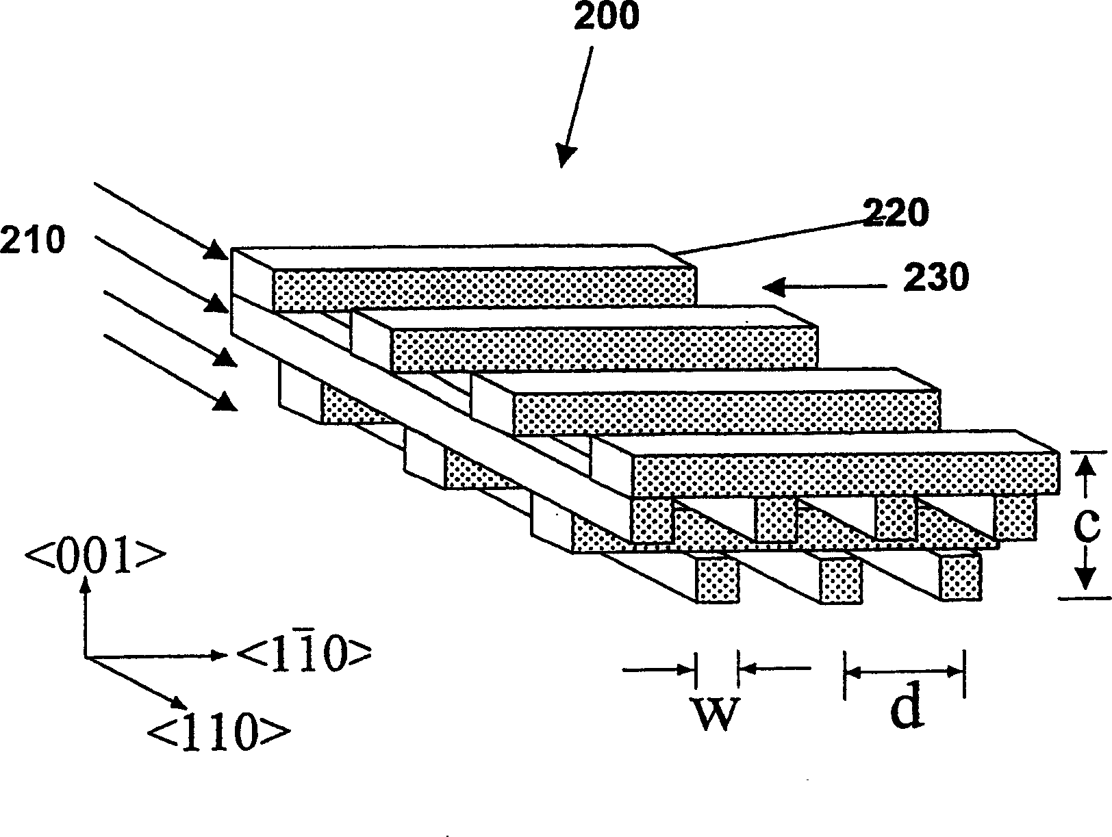
[0020] The present invention relates to a photonically engineered incandescent emitter that is more efficient than conventional incandescent lamps, and a method of making the same. The more efficient incandescent emitters of the present invention are achieved by using photonic engineered structures to improve the emission selectivity of high temperature emitters. Photonic engineered structures consist of materials with periodic variations on the order of the wavelength of light. Periodic variations alter the permissible light patterns in the medium, bringing about many varied and useful properties. Some photonic structures completely cancel light modes in all directions at specific wavelengths. These structures are said to exhibit three-dimensional (3D) photonic band gaps. Photonic Crystals: Molding the Flow of Light (1995) by Joannopoulos et al. describes photonic crystals and their properties.

[0021] Therefore, the thermal emission spectrum and emissivity can be altered...


PUM

PropertyMeasurementUnit
thicknessaaaaaaaaaa
reflectanceaaaaaaaaaa

Abstract

photonically engineered incandescence is disclosed. The emitter materials and photonic crystal structure can be chosen to modify or suppress thermal radiation above a cutoff wavelength, causing the emitter to selectively emit in the visible and near-infrared portions of the spectrum. An efficient incandescent lamp is enabled thereby. A method for fabricating a three-dimensional photonic crystal of a structural material, suitable for the incandescent emitter, is also disclosed.

Description

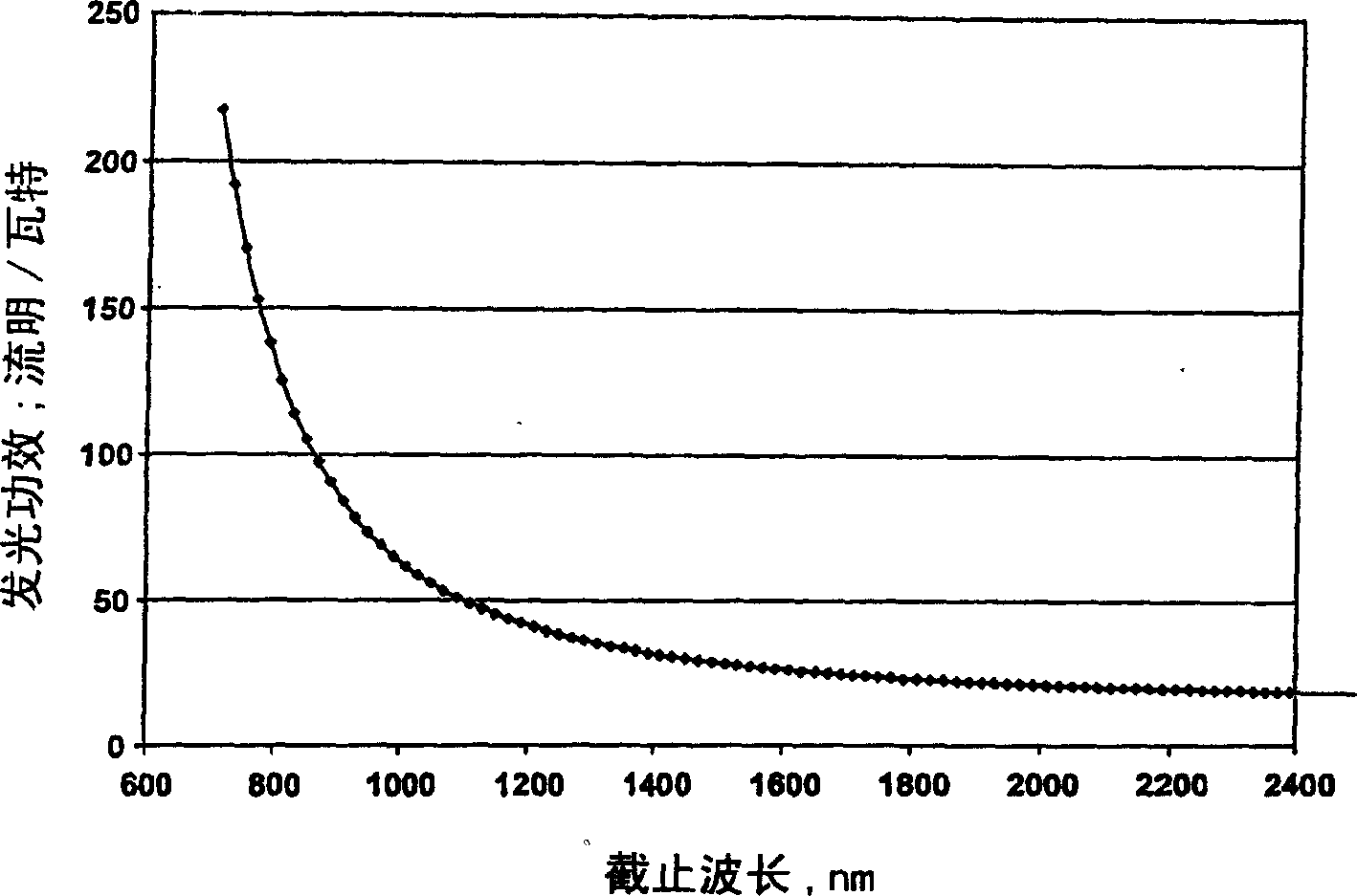
[0001] This invention was made under Contract No. 5 DE-AC04-94AL85000 awarded to Sandi Corporation by the US Department of Energy. The government has certain rights in this invention. technical field [0002] This invention relates to incandescent lamps and, more particularly, to incandescent lamps made from photonically engineered thermal emitters. Background technique [0003] Incandescent bulbs provide high-quality lighting at an affordable price and are the most popular residential lighting technology. Unfortunately, incandescent lighting is also the least efficient (useful light energy) lighting technology in commercial lighting today. A good review of incandescent technology is given in the following article - Bergman et al., Filament Lamps, General Electric Research and Development Center, Report 98CRD027, February 1998. [0004] The lighting industry often uses the term luminous efficacy to describe the efficiency of lamps. Luminous efficacy is often defined as lu...

Claims


Application Information

Patent Timeline
Patent Type & Authority Applications(China)
IPC IPC(8): H01K1/02H01K1/04H01K3/02H01L33/02
CPCH01K3/02H01L33/02H01K1/04H01K1/50
Inventor 詹姆斯·M·吉林绍宇詹姆斯·G·弗莱明詹姆斯·B·莫雷诺
Owner SANDIA
Learn More