
QPSK demodulation with soft outputs for third generation tdd systems

A demodulation method and technology of a demodulation device are applied in the field of communication systems and can solve the problems of complex soft output generation process and the like

Inactive Publication Date: 2004-12-01
LG ELECTRONICS INC
View PDF0 Cites 0 Cited by
  • Summary
  • Abstract
  • Description
  • Claims
  • Application Information

AI Technical Summary

Problems solved by technology

As such, the soft output generation process is too complex and requires too many computational processes for adoption in TDD HCR / LCR

Method used


Image

  • QPSK demodulation with soft outputs for third generation tdd systems
  • QPSK demodulation with soft outputs for third generation tdd systems
  • QPSK demodulation with soft outputs for third generation tdd systems

Examples


Embodiment Construction

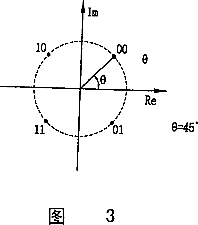
[0028] Figure 3 illustrates a phase shifted symbol constellation in accordance with the present invention. In this example, the phase shift shown is 45° clockwise. However, different angles and / or directions of rotation may be used as desired. By using this or other phase-shifted constellation diagrams according to the invention, the I and Q components can be extracted directly from the real and imaginary axes.

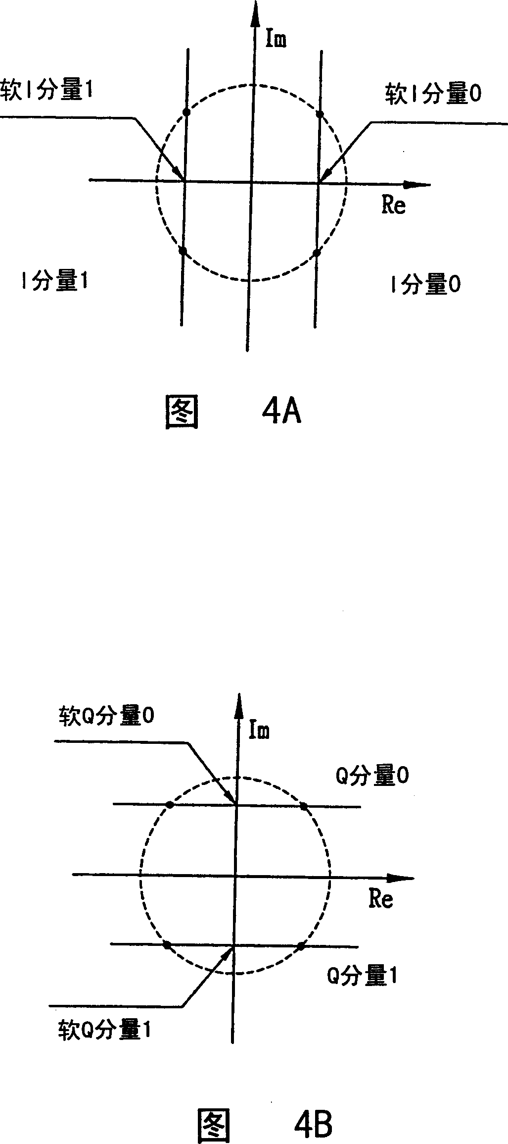
[0029] In other words, as shown in FIG. 4A, according to the imaginary axis, the I component value of the symbol located on the right (first or fourth quadrant) is "0", and the value of the I component of the symbol located on the left (second or third quadrant) is The I component value is "1".

[0030] As shown in Figure 4B, according to the real axis, the Q component value of the symbol located above (the first or second quadrant) is "0", and the Q component value of the symbol located below (the third or fourth quadrant) is " 1". In BPSK modulation, generally, ...


PUM


Abstract

A QPSK demodulation method and apparatus for a soft output in a 3G TDD HCR / LCR system calculates a position of a receiving symbol on a constellation and phase shifts the calculated symbol position. The phase shifted symbol position is then calculated, and the result is amplitude compensated. A soft output of an I component is calculated by subtracting an I component value and Q component value of the calculated symbol position, and a soft output of a Q component is calculated by adding I component value and Q component value. Thus, soft outputs of receiving bit data can be obtained from a simple calculation in QPSK demodulation of the TDD system.

Description

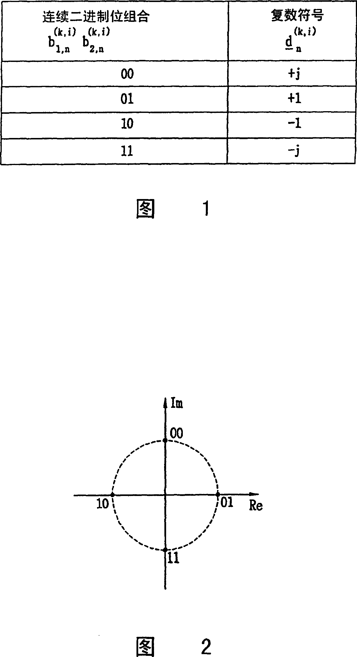
technical field [0001] The present invention generally relates to communication systems, and more particularly to systems and methods for performing QPSK modulation in 3G TDD (Third Generation Time Division Duplex) systems. Background technique [0002] 3G TDD HCR (High Chip Rate) / LCR (Low Chip Rate) systems usually use QPSK (Quadrature Phase Shift Keying) modulation to transmit a signal. This modulation is achieved as follows. [0003] When bit data generated through the physical channel mapping process is QPSK modulated, two bits are mapped to one QPSK symbol. Each user burst (i.e. modulated symbol) used in TDD HCR / LCR consists of two data parts (i=1, 2) and can be expressed as a data block of the following formula (1): [0004] d ¯ ( k , i ) = ( ...

Claims


Application Information

Patent Timeline
IPC IPC(8): H04L27/20H04L27/22H04L27/34
CPCH04L27/22A01K61/73E02B3/046E02B3/043
Inventor 张锡一
Owner LG ELECTRONICS INC
Learn More