Image decoding unit, image encoding/ decoding devices using image decoding unit, and method thereof
An image decoding and encoding technology, applied in the high-speed field, can solve problems such as insufficient response to motion compensation
- Summary
- Abstract
- Description
- Claims
- Application Information
AI Technical Summary
Problems solved by technology
Method used
Image

Examples
no. 1 Embodiment
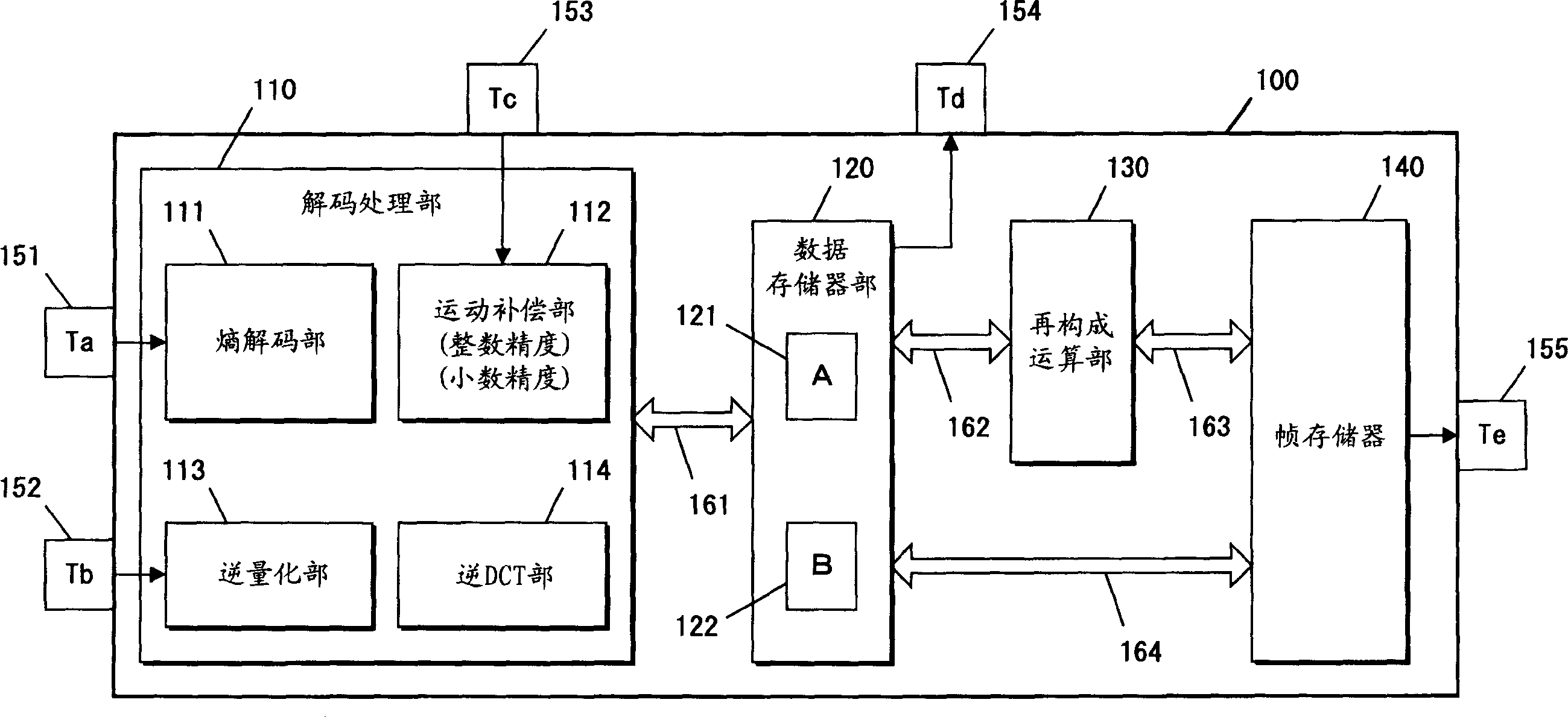
[0107] image 3 It is a structural diagram of the image decoding unit 100 in the first embodiment of the present invention. The image decoding unit 100 of this embodiment includes: a decoding processing unit 110, a data storage unit 120, a reconstruction operation unit 130, and a frame memory 140. The decoding processing unit 110 has an entropy decoding unit 111, a motion compensation unit 112, and an inverse quantization unit. 113. An inverse DCT section 114. The data storage section 120 has a data storage A121 and a data storage B122.
[0108] Furthermore, the decoding processing unit 110 is connected to the data memory unit 120 via a data bus 161. The data memory unit 120 is further connected to the reconstruction computing unit 130 via a data bus 162, and connected to the frame memory 140 via a data bus 164. The reconstruction computing unit 130 is further connected to the frame memory 140 via the data bus 163.
[0109] Moreover, the image decoding unit 100 of the present inv...
no. 2 Embodiment
[0131] Figure 4 It is a block diagram of an image coding apparatus in the second embodiment of the present invention. The image encoding device of this embodiment includes an input terminal 201, an output terminal 202, an image decoding unit 100, a subtraction calculation unit 210, a DCT unit 212, a quantization unit 213, an entropy encoding unit 214, a transmission buffer 215, and a motion detection unit 216.
[0132] The input terminal 201 is connected to the input of the subtraction calculation section 210 and the input of the motion detection section 216, the other input of the subtraction calculation section 210 is connected to the terminal Td154 of the image decoding unit 100, and the output of the subtraction calculation section 210 is connected to the input of the quantization section 213 . The output of the quantization section 213 is connected to the input of the entropy encoding section 214 and the terminal Tb152 of the image decoding unit 100. The other input of the ...
no. 3 Embodiment
[0140] Figure 5 It is a structural diagram of an image decoding device in the third embodiment of the present invention. The image decoding device of this embodiment includes an input terminal 301, a receiving buffer 310, and an image decoding unit 100. The input terminal 301 is connected to the input of the receiving buffer 310, and the output of the receiving buffer 310 is connected to the terminal Ta151 of the image decoding unit 100. Also, the terminal Te155 of the image decoding unit 100 is connected to an external image display device 320. The terminal Tb152, the terminal Tc153, and the terminal Td154 of the image decoding unit 100 are not connected at all.
[0141] Figure 5 The image decoding unit 100 shown, and image 3 The structure and function of the image decoding unit 100 shown are completely the same, and the same reference numerals are assigned to the respective structural elements, and the description is omitted.
[0142] The outline of the operation of the ima...
PUM
 Abstract
Description
Claims
Application Information
 - R&D
- Intellectual Property
- Life Sciences
- Materials
- Tech Scout
- Unparalleled Data Quality
- Higher Quality Content
- 60% Fewer Hallucinations
Browse by: Latest US Patents, China's latest patents, Technical Efficacy Thesaurus, Application Domain, Technology Topic, Popular Technical Reports.
© 2025 PatSnap. All rights reserved.Legal|Privacy policy|Modern Slavery Act Transparency Statement|Sitemap|About US| Contact US: help@patsnap.com