Active organic electroluminescence displaynig unit

A technology of electroluminescence and display unit, applied in static indicators, instruments, etc., which can solve the problems of drive transistor T2 collapse and damage, shortened service life, and increase in current, so as to avoid component temperature rise and improve collapse and damage , Improve the effect of performance degradation

Inactive Publication Date: 2004-12-08
AU OPTRONICS CORP
View PDF0 Cites 10 Cited by
  • Summary
  • Abstract
  • Description
  • Claims
  • Application Information

AI Technical Summary

Problems solved by technology

However, the long-term current flow will increase the threshold voltage of the driving transistor T2 and cause the characteristics of the device to deteriorate. Therefore, with the accumulation of usage time, the amount of current will gradually decrease, resulting in the problem that the brightness of the organic light emitting diode 1 will decrease. , and shorten the service life of the product
[0006] As mentioned above, only a single drive transistor T2 is used in the active organic electroluminescent display unit in the prior art to control the current to drive the machine light emitting diode 1 to emit light.
Therefore, another shortcoming of the circuit structure of the prior art is: when the above-mentioned drive transistor T2 is always in the open (turn on) state, the current passing through the transistor will generate heat energy and make the temperature increase, and cause the critical voltage of the transistor to drop; , which will increase the amount of current flowing through the transistor, and then generate heat energy and increase the temperature of the transistor components; this vicious cycle often causes the drive transistor T2 to eventually collapse due to overheating and damage

Method used


Image

  • Active organic electroluminescence displaynig unit
  • Active organic electroluminescence displaynig unit
  • Active organic electroluminescence displaynig unit

Examples


Embodiment Construction

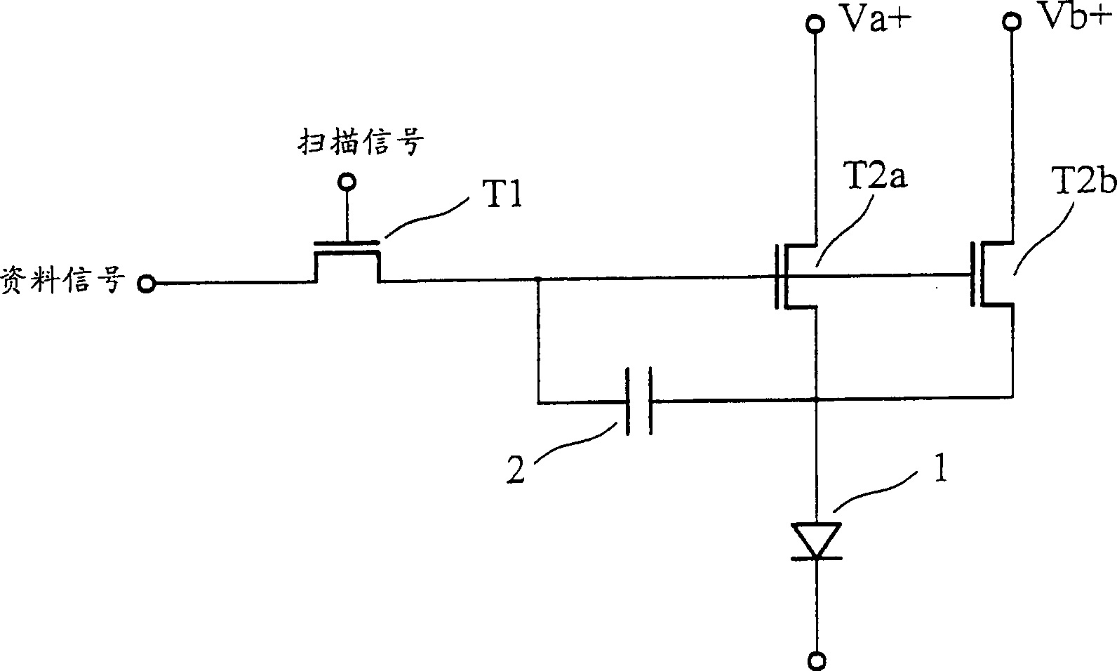
[0025] First please refer to figure 2 , which is a schematic diagram of the circuit structure of the active organic electroluminescence display unit of the present invention. As shown in the figure, the main components in the display unit include an organic light emitting diode 1 , a switching transistor T1 , a first driving transistor T2 a , a second driving transistor T2 b and a capacitor 2 . Generally speaking, the switching transistor T1 , the first driving transistor T2 a and the second driving transistor T2 b may be in the form of a thin-film transistor (Thin-Film Transistor, TFT) in the prior art.

[0026] Wherein, the above-mentioned switch transistor T1 is coupled to a data signal (Data line) at the drain terminal, and a scan signal (Scan line) is coupled to the gate terminal, and the conduction of the switch transistor T1 is controlled by the input scan signal; in addition, the switch The source of the transistor T1 is coupled to the gate of the driving transistor ...


PUM


Abstract

The unit includes an organic light-emitting diode, a first drive transistor, a second drive transistor and a switch transistor. The first drive transistor is coupled between anode of organic light-emitting diode and first voltage source in first waveform. The second drive transistor is coupled between anode of organic light-emitting diode and second voltage source in second waveform. The switch transistor is coupled to grid electrodes of the first and second drives transistors. Thus, switch transistor in on state enables first and second drives transistors. Voltage in first waveform and voltage in second waveform are complemented so as to provide drive current for organic light-emitting diode through first and second drive transistors alternately.

Description

technical field [0001] The invention relates to an active organic electroluminescent display unit, in particular to an active organic electroluminescent display unit which can improve service life. Background technique [0002] Organic electroluminescent displays (organic electroluminescent devices) are also called organic light emitting diode (organic light emitting diode, OLED) displays. Because it has the characteristics of self-emission (selfemission) and can be displayed in an array, it does not need to set a backlight; in addition, the organic electroluminescent display has the advantages of thin thickness, high contrast, low power consumption, high resolution, and no viewing angle limitation. Therefore, it is regarded as a next-generation flat panel display. [0003] Taking an active organic electroluminescent display in the prior art as an example, the principle is to drive an organic light emitting diode (OLED) to emit light by an electric current. First please re...

Claims


Application Information

Patent Timeline
Patent Type & Authority Applications(China)
IPC IPC(8): G09G3/00G09G3/30G09G3/3225
Inventor 利锦洲李纯怀
Owner AU OPTRONICS CORP
Why Eureka
Try Eureka