Check patentability & draft patents in minutes with Patsnap Eureka AI!

Wireless terminal

A wireless terminal and terminal technology, applied in antennas, antenna parts, antenna supports/mounting devices, etc., can solve the problems of not improving the overall performance of the terminal, shortening battery life, etc.

Inactive Publication Date: 2004-12-08
NXP BV
View PDF1 Cites 6 Cited by
  • Summary
  • Abstract
  • Description
  • Claims
  • Application Information

AI Technical Summary

Problems solved by technology

Energy loss radiated to the human body represents a waste of energy that will uselessly shorten battery life prematurely without improving the overall performance of the terminal

Method used


Image

  • Wireless terminal
  • Wireless terminal
  • Wireless terminal

Examples


Embodiment Construction

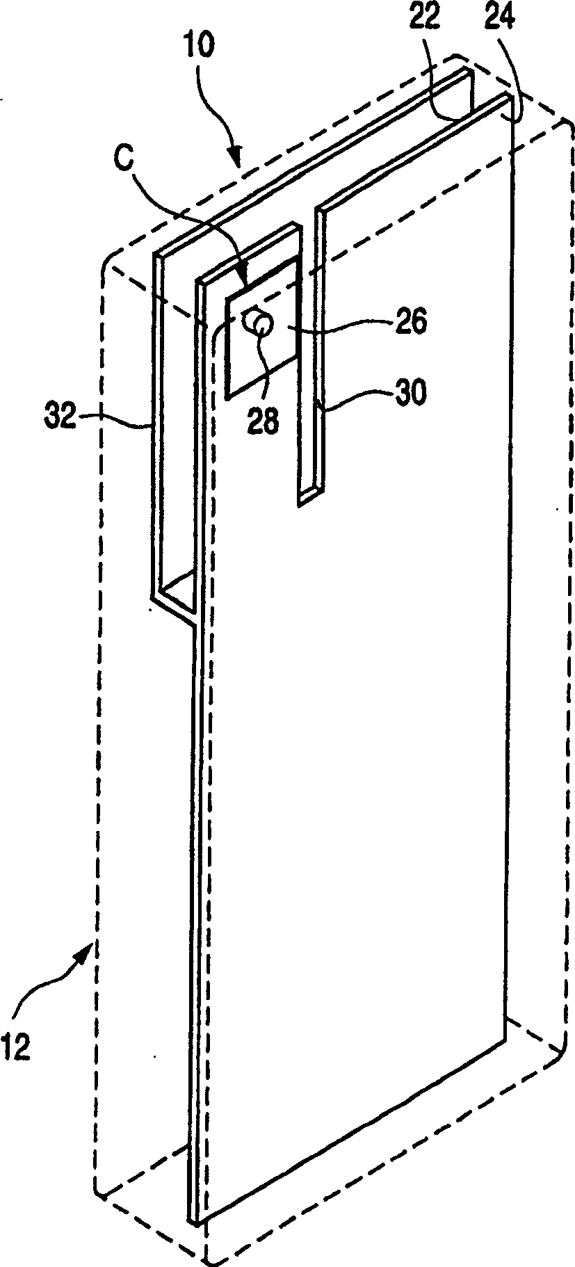
[0021] figure 1 with 2 The illustrated embodiment of the wireless terminal includes a capacitive feedback coupled handset 10, suitable for use as a cellular or cordless telephone. The handset 10 has an outer plastic casing 12 shown in dotted lines and has a small hole 14 on its front panel for receiving a microphone (not shown) and a small hole 16 for connecting a speaker (not shown). Out), there is also an LCD screen 18 and a keyboard 20.

[0022] Inside the housing 12 is mounted an elongated printed circuit board 22, on at least one surface of which is arranged the electronic components (not shown) required for controlling the handset 10 and for processing received speech and data signals. The other side of the circuit board 22 facing the back of the handset is at least partially metallized to provide a ground plane 24 .

[0023] The mobile phone shown does not have a dedicated independent antenna, but has a small feedback coupling capacitor C designed to have a large cap...


PUM


Abstract

A capacitively back-coupled wireless terminal ( 10 ) comprises a PCB ( 22 ) having a ground conductor ( 24 ) on one surface. A back coupling capacitor (C) is carried by the ground conductor. An elongate slot ( 30 ) is provided in the ground conductor to widen the bandwidth. An electromagnetic shield ( 32 ) is provided on the side of the PCB ( 22 ) which in use is facing a lossy dielectric in order to reduce the SAR. The shield is disposed adjacent to, but spaced from, the slot ( 30 ) in the ground conductor and the back coupling capacitor. For narrowband operation the slot may be omitted and / or the spacing between the PCB ( 22 ) and the shield ( 32 ) may be reduced.

Description

technical field [0001] The present invention relates to a wireless terminal which may be used particularly, but not exclusively, as a cellular telephone or as a low power remote control terminal. More specifically, the present invention relates to a wireless terminal with a planar antenna. Background technique [0002] Generally, low SAR (Specific Absorption Rate) characteristics are provided in hand-held terminals such as mobile phones using planar inverted-F antennas (PIFAs) or the like. A PIFA must have a relatively large distance, typically 8mm, between its top pad and the supporting PCB in order to have sufficient bandwidth for GSM (900MHz) and DCS (1800MHz) operation. This limits the thickness of the mobile phone. [0003] International patent application WO 02 / 13306 (applicant docket PHGB 010056WO) discloses a method of widening the bandwidth of a wireless communication terminal using a mobile phone as a transmitter. More specifically, the antenna is replaced by a ...

Claims


Application Information

Patent Timeline
IPC IPC(8): H01Q13/08H01Q1/24H04M1/02H05K1/02
CPCH05K1/0218H05K1/0231H01Q1/243H01Q1/245H04B1/38
Inventor K·R·博伊勒P·J·马塞伊
Owner NXP BV
Features
  • R&D
  • Intellectual Property
  • Life Sciences
  • Materials
  • Tech Scout
  • Unparalleled Data Quality
  • Higher Quality Content
  • 60% Fewer Hallucinations
Learn More