Method for correcting workpiece crosssection shape of pipe bended by pipe bending machine
A technology of cross-sectional shape and pipe bending machine, which is applied in the field of correction of the cross-sectional shape of the workpiece of the pipe bending machine, can solve the problems such as the influence of deformation and rebound amount and deformation quality, etc., and achieves improved strength, reduced frictional resistance, and small contact area. Effect
- Summary
- Abstract
- Description
- Claims
- Application Information
AI Technical Summary
Problems solved by technology
Method used
Image

Examples
Embodiment 1
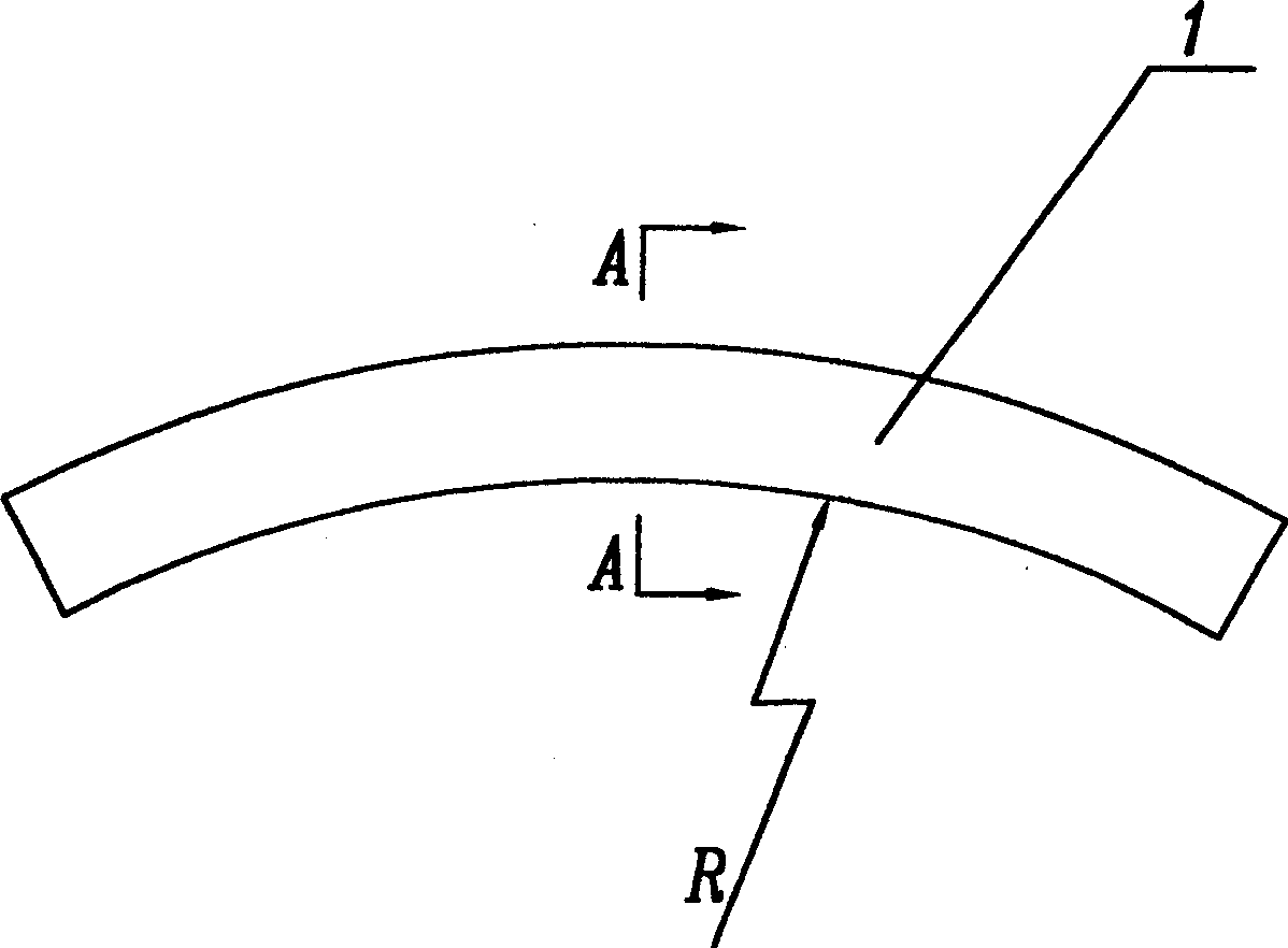
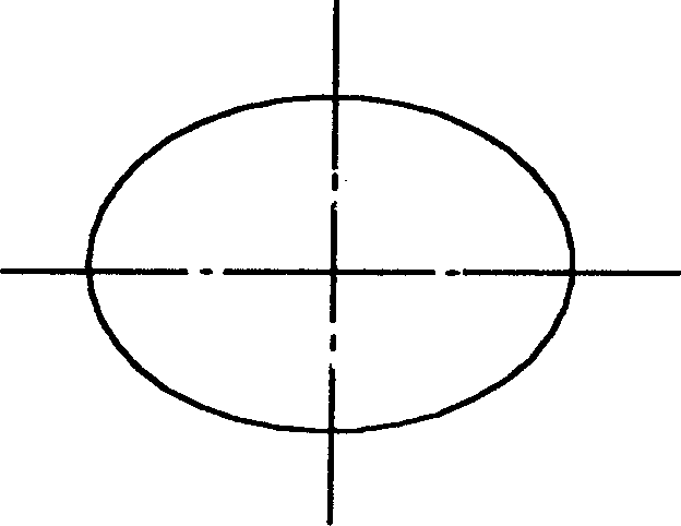
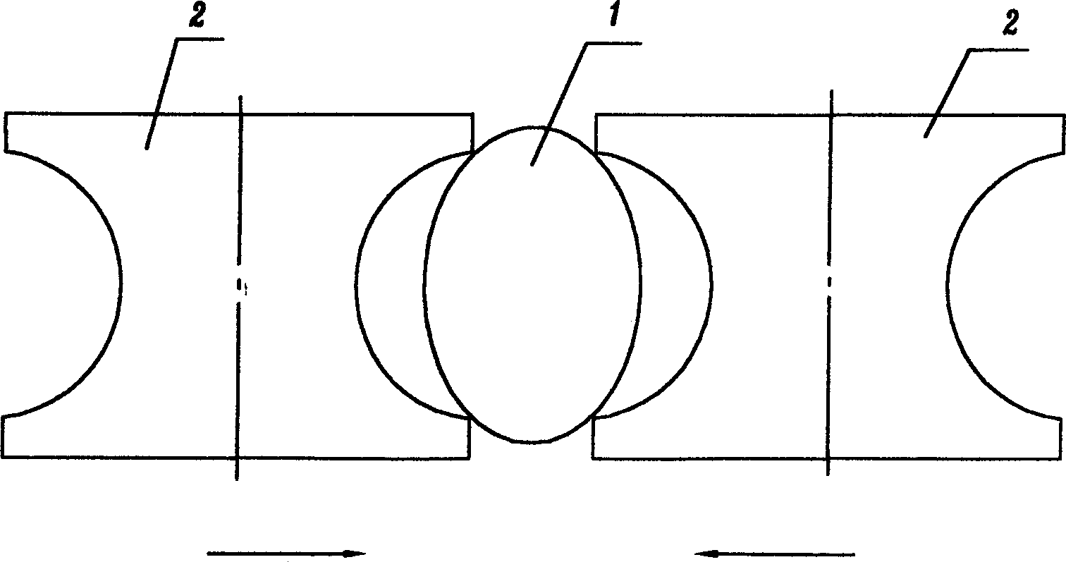
[0021] Embodiment 1: as Figure 4 As shown, the method for correcting the cross-sectional shape of the workpiece of the pipe bender uses a pair of correcting molds to correct the workpiece. The correcting mold is set after the workpiece of the pipe bender is bent; The movement direction of the workpiece is along the long axis direction after the deformation of the workpiece section, and the generatrix of the correction mold is a curve. When the curve is an arc, its arc is less than 180 degrees;
[0022] The correction force of the correction mold is a pair of correction internal forces of equal size and opposite directions. The center of symmetry of the correction mold is in the plane of the minor axis, and the center of symmetry remains unchanged during the correction process;
[0023] The rotation axis of the correction mold itself is manually or automatically adjusted and placed in the normal direction of the bending center line of the bend, that is, the radius R direction ...
Embodiment 2
[0024] Embodiment 2: as Figure 5 As shown, the correction method of the cross-sectional shape of the workpiece of the pipe bender uses 1 pair of correction rollers to correct the workpiece. The correction rollers are set after the workpiece of the pipe bender is bent; The movement direction of the workpiece is along the long axis direction after the deformation of the workpiece section, and the generatrix of the correction roller is a straight line;
[0025] The correcting force of the correcting roller is a pair of correcting internal forces of equal size and opposite directions. The center of symmetry of the correcting roller is in the plane of the short axis, and the center of symmetry remains unchanged during the correction process.
Embodiment 3
[0026] Embodiment 3: The initial cross-section of the workpiece is circular, and the correction method for the cross-sectional shape of the workpiece of the pipe bender uses a pair of correction molds to reverse the deformation of the workpiece. The correction mold is set before the workpiece of the pipe bender is bent; After the two sides of the long axis, the direction of movement of the correction mold will be along the direction of the long axis of the workpiece section after deformation. Other is identical with embodiment 1, embodiment 2.
PUM
 Abstract
Description
Claims
Application Information
 - Generate Ideas
- Intellectual Property
- Life Sciences
- Materials
- Tech Scout
- Unparalleled Data Quality
- Higher Quality Content
- 60% Fewer Hallucinations
Browse by: Latest US Patents, China's latest patents, Technical Efficacy Thesaurus, Application Domain, Technology Topic, Popular Technical Reports.
© 2025 PatSnap. All rights reserved.Legal|Privacy policy|Modern Slavery Act Transparency Statement|Sitemap|About US| Contact US: help@patsnap.com