

Two-purpose lighting vehicle driven by electrically or manually
A lighting vehicle and vehicle body technology, which is applied to vehicle components, searchlight transportation, control devices, etc., can solve the problems of heavy load, unsafety, and low efficiency of the vehicle body, and achieve convenient installation and disassembly, safe and reliable walking, and high efficiency. high effect
- Summary
- Abstract
- Description
- Claims
- Application Information
AI Technical Summary
Problems solved by technology
Method used
Image

Examples
Embodiment Construction
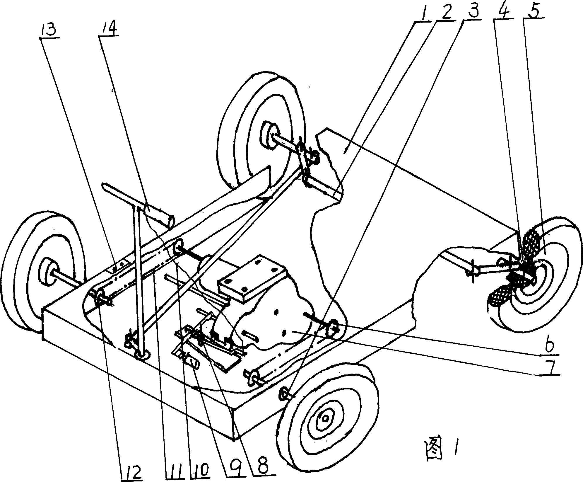
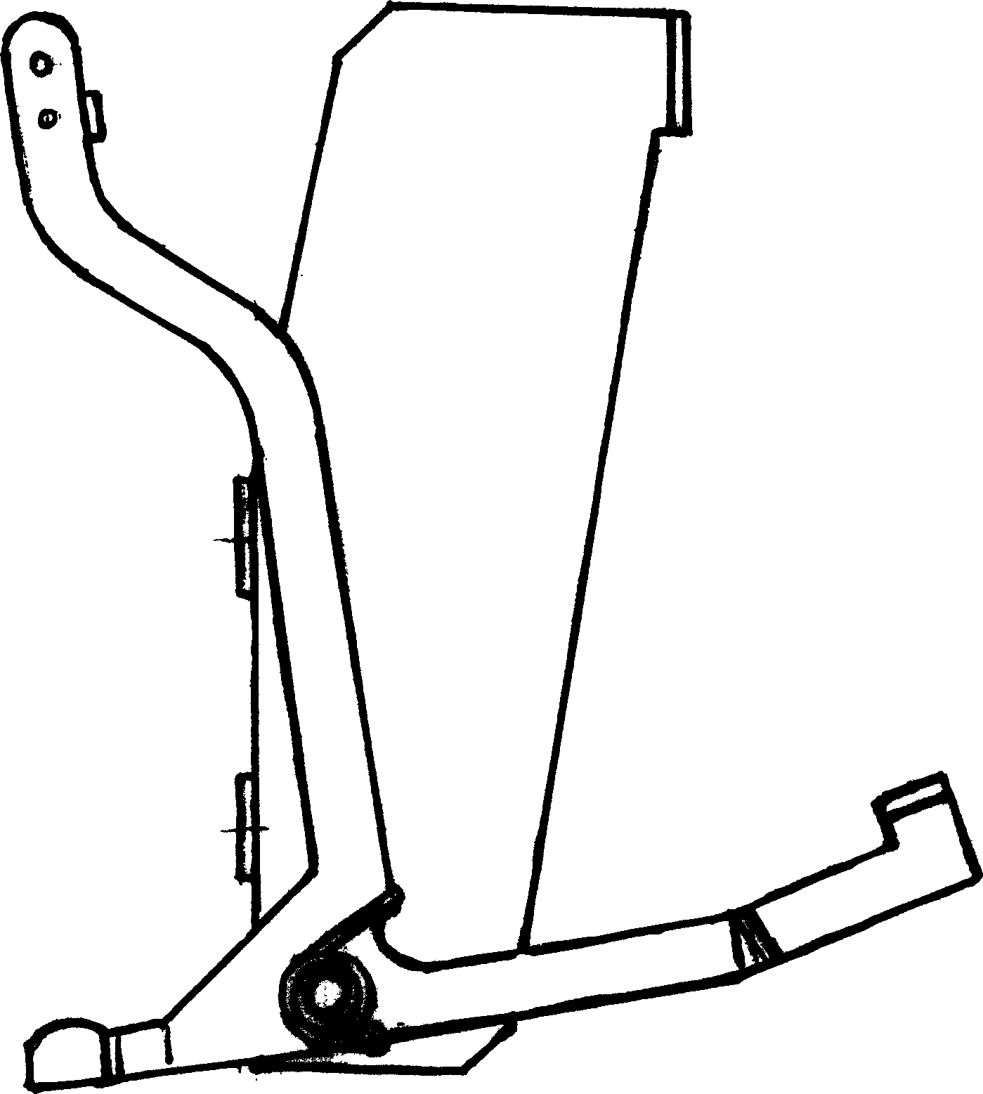
[0010] In order to further understand the characteristics and effects of the invention of the present invention, the following embodiments are given as examples, and detailed descriptions are as follows in conjunction with the accompanying drawings. Please refer to Fig. 1, figure 2 .
[0011] Figure 1, figure 2 Shown: the chassis 1 of the illuminating car body for both manual and electric walking uses screws to fix the reducer 7, and the side of the reducer 7 fixes the special-shaped connecting rod 8; one end of the steel wire 10 is fixed on the handlebar 14, and the other end is fixed with a screw. Be fixed on the special-shaped connecting rod 8. When electric walking, twist the handlebar 14, tighten the steel wire 10 and then the special-shaped connecting rod 8 swings around the fulcrum. 9 is closed, because two sprockets 6 are fixed on the output shaft of the reducer 7, it is connected with the sprocket 12 on the rear axle 3 of the car body through the chain 11 to make th...
PUM
 Abstract
Description
Claims
Application Information