Double-locking trap

A trap and double-locking technology, applied in steam traps, mechanical equipment, etc., can solve the problems of insufficient locking force on the sealing surface, slow response speed of the floating ball, slow opening action, etc., to achieve improved sealing performance and simple structure , The effect of fast opening and closing speed

Inactive Publication Date: 2005-01-05
周杰仁
View PDF1 Cites 5 Cited by
  • Summary
  • Abstract
  • Description
  • Claims
  • Application Information

AI Technical Summary

Problems solved by technology

Although the patent of this structure has made some progress compared with the existing technology, there are still defects: the tension force when the valve core is closed is too small, the locking force of the sealing surface is not enough, the sealing performance is poor, and the high temperature and high pressure working conditions There is still steam leakage; the response speed of the float ball is slow, the opening action is slow, and the valve body is bulky

Method used


Image

  • Double-locking trap
  • Double-locking trap

Examples


Embodiment Construction

[0015] Embodiments of the present invention are described in further detail below in conjunction with the accompanying drawings:

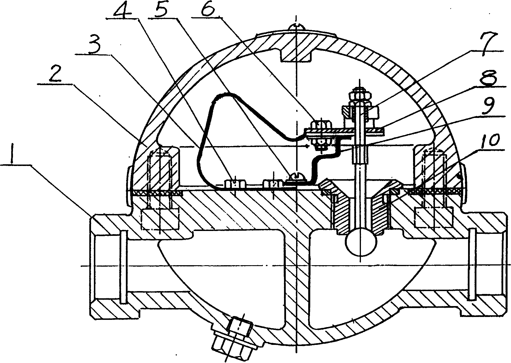
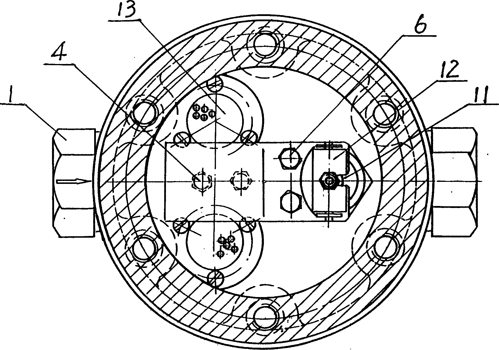
[0016] This embodiment is mainly composed of a valve body 1, a valve casing 2, a "C"-shaped composite metal sheet 3, a plane composite metal sheet 8, a support sheet 9, a valve core 7, and a valve seat 10. "C"-shaped composite metal sheet 3, flat composite metal sheet 8, support sheet 9, and valve core 7 are set in the valve chamber composed of valve body 1 and valve casing 2, and the valve seat 10 is placed in the valve body at the outlet of the valve chamber. 1, the valve core 7 is placed in the valve seat 10, and can move up and down in the valve seat 10. The upper end of the spool 7 and the flat composite metal sheet 8 are connected by a shifting fork, and the lower end of the spool 7 passes through the valve seat 10, so that the sealing surface formed between the spool 7 and the valve seat 10 is set on the valve seat. 10 The lower port of the...


PUM


Abstract

The invention relates to a double-lock drainage valve, the cavity formed by the valve and the shell has a valve core, valve base and a flat compound metal plate which is heat-variable deformation, 'C' type compound metal plate and supporting plate, the sealed surface of the valve core and the base is arranged at the lower part of the valve base, the 'C' type compound metal plate is fixed on the valve, the upper side of the 'C' type compound metal plate is connected to the flat compound metal plate directly, the supporting plate is arranged on the lower part of the flat compound metal and acts supporting effect. The flat compound metal plate and the valve core are connected together with shifting yoke mode. When the temperature in the cavity changes, the 'C' type plate and the flat compound metal plate shift the valve core to move up and down, thus control the valve to be opened or closed. The invention has a large lock force, the volume of the valve is small.

Description

technical field [0001] The invention relates to a valve, in particular to a double locking steam trap. Background technique [0002] Steam trap is an automatic valve, also called steam blocking and draining valve, which is mainly used to automatically remove condensed water on steam heating equipment or pipelines to prevent steam leakage and loss. [0003] The valve is a normally open valve at normal temperature, and a normally closed valve at high temperature. According to the change of condensed water in the valve cavity, the valve core is opened or closed by elastic or thermal elements. Thus, the condensed water in the steam equipment and the steam pipe network can be automatically and timely removed. When the steam in the pipe network enters the valve chamber, under the action of the elastic force or deformation force of the elastic or heat-sensitive element, the valve core is driven to close the valve. When a certain amount of condensed water is generated in the pipe ...

Claims


Application Information

Patent Timeline
Patent Type & Authority Applications(China)
IPC IPC(8): F16T1/08
Inventor 周杰仁
Owner 周杰仁
Why Eureka
Try Eureka