

Decontamination equipment for exhaust gas
A technology of exhaust gas purification device and atomization device, which is applied in chemical instruments and methods, separation of dispersed particles, use of liquid separation agent, etc., can solve the problems of large induced draft fan power, complex equipment structure, inconvenient maintenance, etc., and achieve purification Good effect, water saving, simple structure
- Summary
- Abstract
- Description
- Claims
- Application Information
AI Technical Summary
Problems solved by technology
Method used
Image

Examples
Embodiment Construction
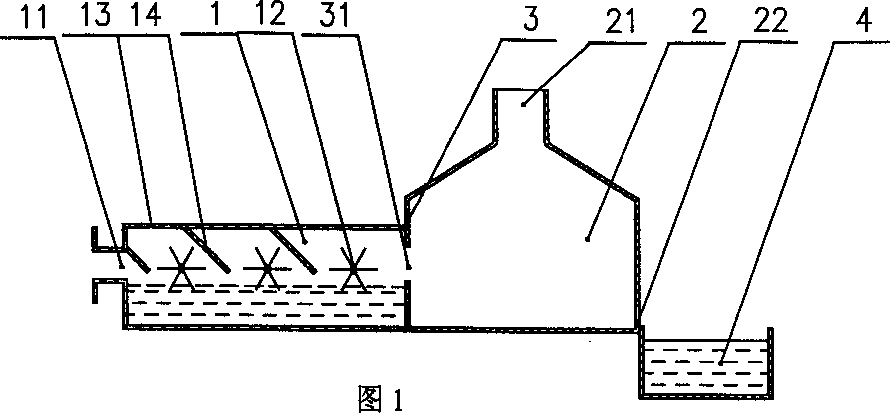
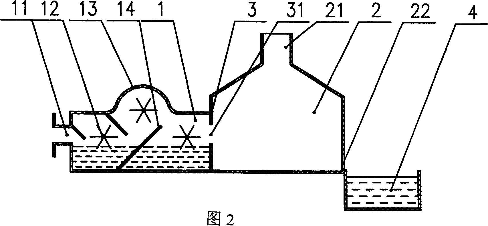
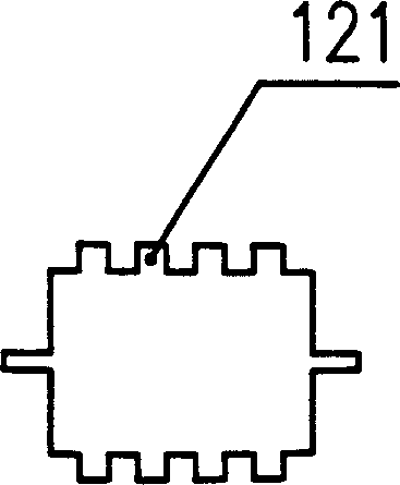
[0017] In the first embodiment shown in Fig. 1, a kind of exhaust gas purification device has aerosol chamber 1, settling chamber 2 and pool 4, a partition 3 is arranged between aerosol chamber 1 and settling chamber 2, and partition 3 A vent 31 is arranged on the top, so that the aerosol chamber 1 communicates with the settling chamber 2. An air inlet 11 is arranged at the end of the aerosol chamber 1. Three impellers 12 are fixed on the inner wall of the aerosol chamber 1, and the three impellers 12 are arranged in a straight line. There are teeth 121 on the impeller 12, and the teeth 121 can be as image 3 , 4 The saw-shaped teeth, triangular teeth, and trapezoidal teeth integrated with the impeller 12 shown in . Teeth 121, there is water in the aerosol chamber 1, the upper part of the aerosol chamber 1 is provided with a water inlet 13, the height of the water surface is 8mm in the contact range between the water and the impeller 12, and a gas baffle 14 is arranged above t...
PUM
 Abstract
Description
Claims
Application Information