Eureka AIR delivers breakthrough ideas for toughest innovation challenges, trusted by R&D personnel around the world.

Rolling wheel sliding rail driving device of rail transit platform gate

A rail transit and driving device technology, which is applied to the suspension device of the wing leaf, door/window accessories, power control mechanism, etc., can solve the problems of strict installation accuracy, high maintenance cost, and large running resistance, etc., and achieve improved Running stability, improving efficiency and reducing running resistance

Pending Publication Date: 2018-05-15
WUHAN LEADDO MEASURING & CONTROL CO LTD
View PDF0 Cites 3 Cited by
  • Summary
  • Abstract
  • Description
  • Claims
  • Application Information

AI Technical Summary

Problems solved by technology

[0004] The existing semi-height safety door driving guide generally adopts linear ball slide rail, and its balls and slide rails are made of carbon steel, which is easy to rust in harsh environments and cause safety door failure
At the same time, its installation accuracy requirements are strict, maintenance costs are high, running resistance is relatively large, and maintenance is inconvenient, etc., which also bring uncertain factors to the running stability of the half-height safety door.

Method used


Image

  • Rolling wheel sliding rail driving device of rail transit platform gate
  • Rolling wheel sliding rail driving device of rail transit platform gate
  • Rolling wheel sliding rail driving device of rail transit platform gate

Examples


Embodiment Construction

[0027] The present invention will be further described in detail below in conjunction with the accompanying drawings and specific embodiments.

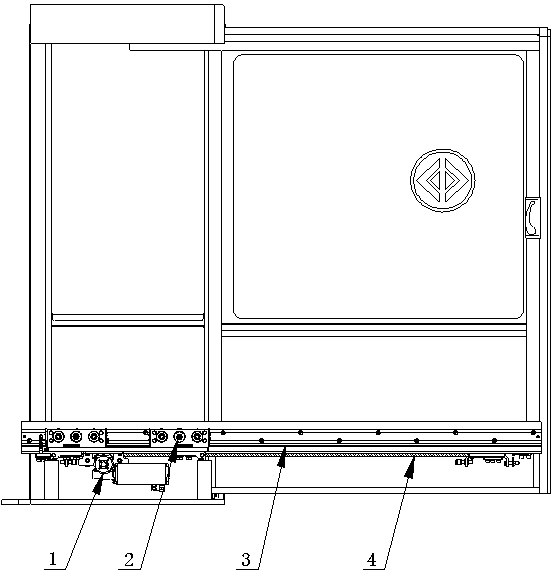
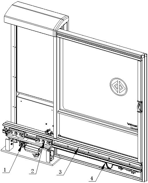
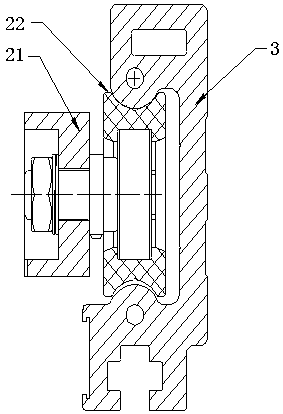
[0028] Such as Figure 1 to Figure 7 As shown, the embodiment of the present invention provides a roller slide rail driving device for a rail transit platform door, comprising a U-shaped slide rail 3 and a roller slider 2, the U-shaped slide rail 3 is installed on the sliding door, and the roller slider 2 is installed on the On the fixed side box; the roller slider 2 is connected with the semicircular mandrel of the U-shaped slide rail 3 through the concentric roller 22 and the eccentric roller 23 to form a set of relative motion rolling pairs; the concentric roller 22 and the eccentric roller 23 are radially They are on the same straight line and are distributed in a triangular shape in the axial direction, each of which plays the role of load bearing and guiding. The vertical position of the eccentric roller 23 can be adjusted to re...


PUM


Abstract

The invention relates to the field of rail transit platform gates, and provides a rolling wheel sliding rail driving device of a rail transit platform gate. The rolling wheel sliding rail driving device of the rail transit platform gate comprises a power mechanism, rolling wheel sliding blocks, a U-shaped sliding rail and a toothed belt driving mechanism. The power mechanism comprises a sliding block support, a motor support and a driving motor, wherein the motor support is fixedly connected with the sliding block support, and the driving motor is installed on the motor support. Each rolling wheel sliding block comprises a sliding block body, concentric rolling wheels, an eccentric rolling wheel and dust-preventing scraping plates, wherein the concentric rolling wheels and the eccentric rolling wheel are installed on the sliding block body and matched with the U-shaped sliding rail, and the dust-preventing scraping plates are installed on the two sides of the sliding block body. The U-shaped sliding rail is installed on the sliding gate. The toothed belt driving mechanism is connected with the U-shaped sliding rail, and comprises a toothed belt, a toothed belt clamping end and a toothed belt adjusting end. According to the rolling wheel sliding rail driving device of the rail transit platform gate, big rolling wheels move instead of small rolling balls, and therefore the running resistance is reduced, and the running stability is improved. Meanwhile, the rolling wheel sliding rail driving device of the rail transit platform gate further has the advantages of being quiet, being free of noise, pollution and maintenance, and being easy to install and adjust. The service life of the platform gate is prolonged.

Description

technical field [0001] The invention relates to the field of rail transit platform doors, in particular to a roller slide rail driving device for a half-height safety door of a rail transit platform. Background technique [0002] With the continuous acceleration of China's urbanization process, the rapid advancement of urbanization, especially the expansion of large cities, has brought about the demand for urban transportation. Urban rail transit has the characteristics of safety, comfort, speed, environmental protection, and large transportation volume, so it has become an inevitable trend for the sustainable development of major cities. [0003] As an important part of urban rail transit equipment, platform doors bring a safe and comfortable experience to people's travel. Due to the characteristics of urban rail transit, half-height safety doors are generally installed on ground platforms or elevated platforms, in a semi-open open-air environment, and the weather environm...

Claims


Application Information

Patent Timeline
IPC IPC(8): E05D13/00E05F15/643E05D15/06
CPCE05D13/00E05D15/0686E05F15/643E05Y2900/531
Inventor 孙再明宋宏波陈卫锋
Owner WUHAN LEADDO MEASURING & CONTROL CO LTD
Why Eureka
Eureka Blog
Learn More