Filtering tank capable of fully filter-pressing waste oil

A filter tank and filter screen technology, applied in the field of filter tanks, can solve the problems of oil waste, waste oil filtration loss, unfavorable storage, etc., and achieve the effects of avoiding low efficiency, improving oil recovery rate, and avoiding difficulties

Inactive Publication Date: 2014-12-17
重庆市控能净化设备有限公司
View PDF4 Cites 5 Cited by
  • Summary
  • Abstract
  • Description
  • Claims
  • Application Information

AI Technical Summary

Problems solved by technology

[0004] The problem with this kind of filter tank is: when the mixed waste oil in the heating reactor is exhausted and no subsequent oil is injected into the filter tank, it starts to rely on air pressure to pressurize the liquid level, and the oil level in the filter tank begins to drop , when the filter screen of the filter element is exposed to the oil level, the air is filled into the hollow part of the filter element. Even if the air pressure is increased at this time, the difference between the internal and external air pressure of the filter element is equal, and the filter element cannot press the mixed waste oil. In this way, There is more than half of the unfiltered mixed waste oil in the filter tank. This mixed waste oil contains a large amount of waste residue, which cannot be dumped at will, and is not conducive to storage. get bigger

Method used


Image

  • Filtering tank capable of fully filter-pressing waste oil
  • Filtering tank capable of fully filter-pressing waste oil
  • Filtering tank capable of fully filter-pressing waste oil

Examples


Embodiment 1

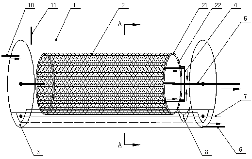
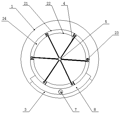
[0020] Such as figure 1 and figure 2 As shown, this embodiment includes a closed tank body 1, and also includes a rotary filter 2, the rotary filter 2 is installed in the tank body 1 through a rotating shaft 5 including an oil outlet, and the outer layer of the rotary filter 2 is The filter screen 21, the inner layer of the rotary filter 2 is a cylinder 22, and the rotating shaft 5 is fixedly connected to the two sides of the cylinder 22 along the center of rotation. area, the percolation area is divided into a plurality of isolated filtration zones 24 by a partition block 23, and each filter zone 24 is equipped with an oil outlet branch pipe 4 with a control valve, and all the oil outlet branch pipes 4 with a control valve are connected to the center of the rotating shaft 5 An oil outlet, an oil inlet pipe 10 and a pressurized air pipe 11 are arranged on the tank body 1 .

[0021] In order to further improve the recovery rate of waste oil and increase the filtering surface...

Embodiment 2

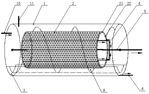
[0024] Such as image 3 As shown, the difference between Embodiment 2 and Embodiment 1 is that a helical blade 9 is installed on the cylindrical surface of the rotary filter 2 . The effect of spiral blade 9 is to promote the waste residue at the bottom of the filter tank. When the rotary filter 2 rotates, the spiral blade 9 pushes the waste residue to one side of the tank body to realize slag removal.


PUM


Abstract

The invention discloses a filtering tank capable of fully filter-pressing waste oil. The filtering tank comprises an airtight tank body and a rotary filter unit, wherein the rotary filter unit is mounted inside the tank body through a rotating shaft provided with an oil outlet hole; the outer layer of the rotary filter unit is provided with a filter screen, and the inner layer of the rotary filter unit is provided with a cylinder; the rotating shaft is fixedly connected onto two side surface of the cylinder along a rotating center; an annular percolating area is formed between the inner side of the filter screen and the outer wall of the cylinder and divided into a plurality of mutually-isolated filtering separated areas through separating blocks, every filtering separated area is provided with an oil outlet branch pipe with a control valve, and all the oil outlet branch pipes with the control valves are communicated with the central oil outlet hole of the rotating shaft; an oil inlet pipe and a pressurizing air pipe are arranged on the tank body. The filtering tank capable of fully filter-pressing the waste oil has the advantages of being capable of fully filter-pressing the waste oil inside the filtering tank through air pressure filtering, improving the oil recovery rate of waste oil purification equipment and meanwhile automatically cleaning dirt and oil residue attached on the filter screen.

Description

technical field [0001] The invention relates to waste oil purification equipment, in particular to a filter tank in the waste oil purification equipment. Background technique [0002] Waste oil purification equipment is a common device for waste oil regeneration technology. It mainly includes three parts: a heating reactor, a vacuum separator and a filter tank. The heating reactor heats the waste oil at a constant temperature, and at the same time adds flocculants and adsorbents and stir; the waste oil mixed in the heating reactor is sucked into the vacuum separator by the vacuum pump, and the vacuum separator discharges the water and waste gas contained in the waste oil, and filters out some mechanical impurities in the waste oil; After circulating between the tank and the vacuum separator, it is transported from the heating reactor to the filter tank, where the oil and residue are separated to obtain purified clean oil. [0003] The structure of existing canister is as " ...

Claims


Application Information

Patent Timeline
Patent Type & Authority Applications(China)
IPC IPC(8): B01D29/11B01D29/74B01D29/82
Inventor 豆春林
Owner 重庆市控能净化设备有限公司
Why Eureka
Try Eureka