Quantity-of-light adjusting device, optical system having the same, and photographing device

A light quantity adjustment, optical technology, applied in optics, optical components, apertures, etc., can solve problems such as the impact of optical performance

Inactive Publication Date: 2005-01-12
CANON KK
View PDF5 Cites 8 Cited by
  • Summary
  • Abstract
  • Description
  • Claims
  • Application Information

AI Technical Summary

Problems solved by technology

[0012] In addition, the influence of the transmission wavefront retardation on the performance provided is different from the influence of the concentration difference of the adjacent regions of different transmission coefficients of the ND filter on the optical performance provided. The superposition effect of these factors can have a greater impact on the optical performance under certain conditions

Method used


Image

  • Quantity-of-light adjusting device, optical system having the same, and photographing device
  • Quantity-of-light adjusting device, optical system having the same, and photographing device
  • Quantity-of-light adjusting device, optical system having the same, and photographing device

Examples


Embodiment 1

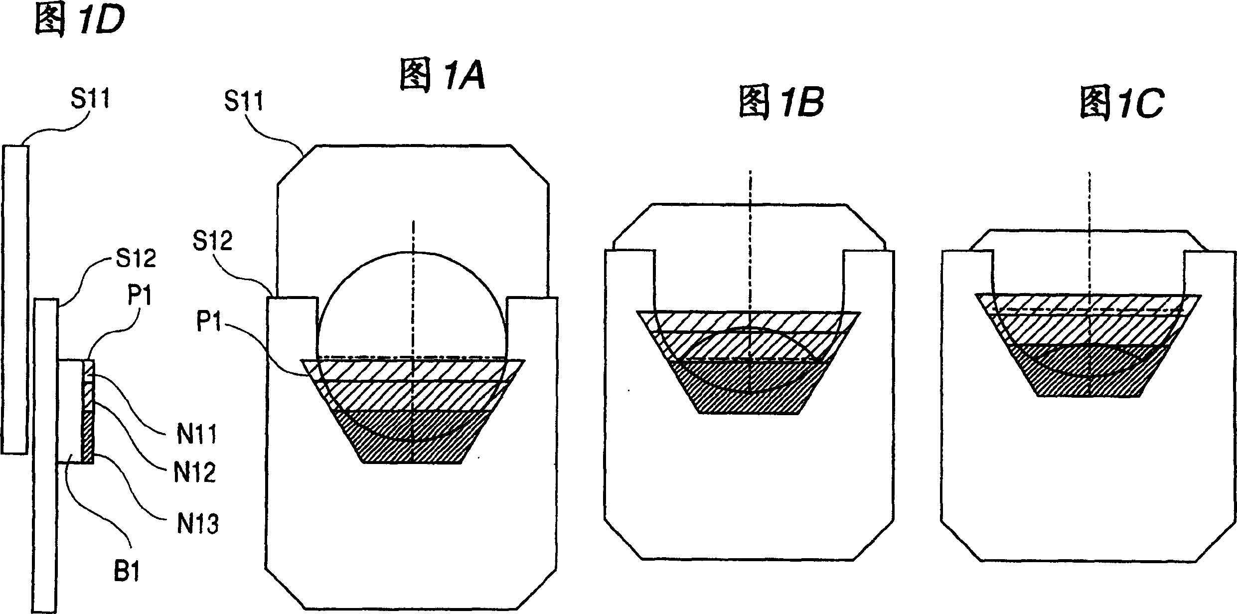
[0121] FIG. 1 shows Embodiment 1 of the present invention. Fig. 1A, Fig. 1B, Fig. 1C, and Fig. 1D are examples of a light quantity adjusting device (diaphragm device) to which the present invention is applied. FIG. 1A shows an open aperture state, FIG. 1B shows an intermediate aperture state, FIG. 1C shows a minimum aperture state, and FIG. 1D shows a side view of FIG. 1A .

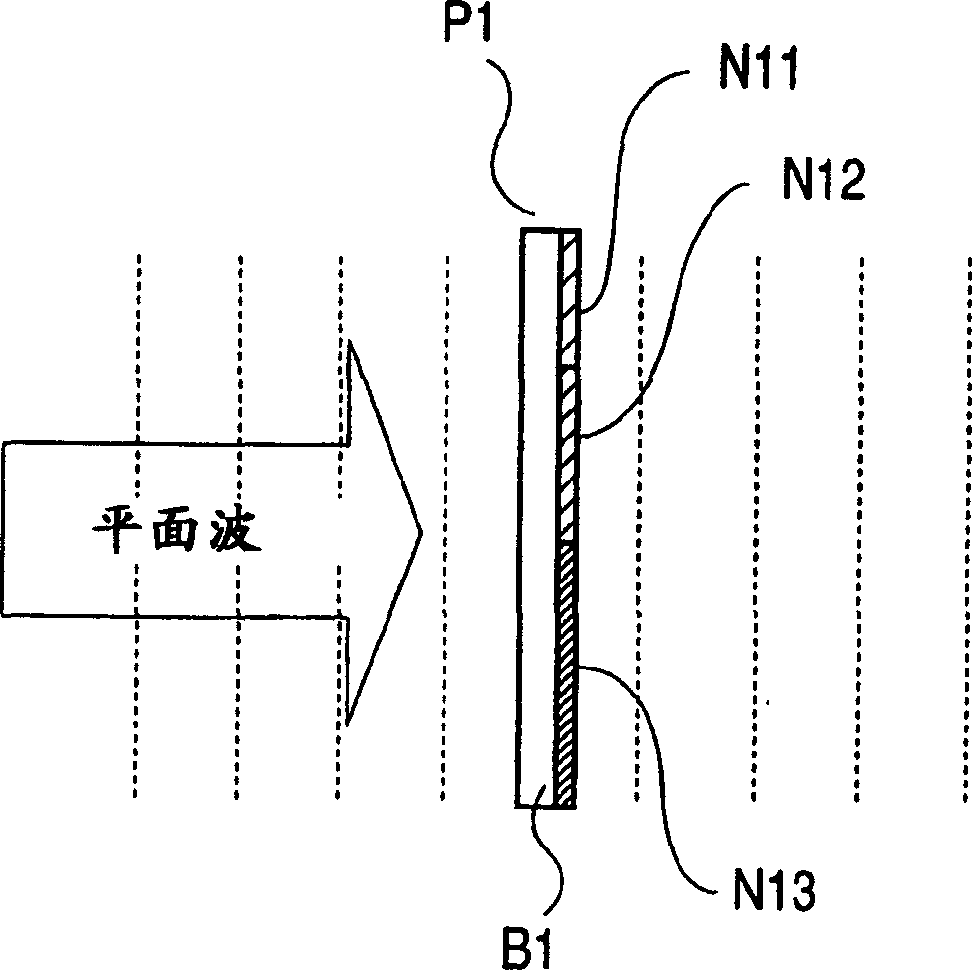
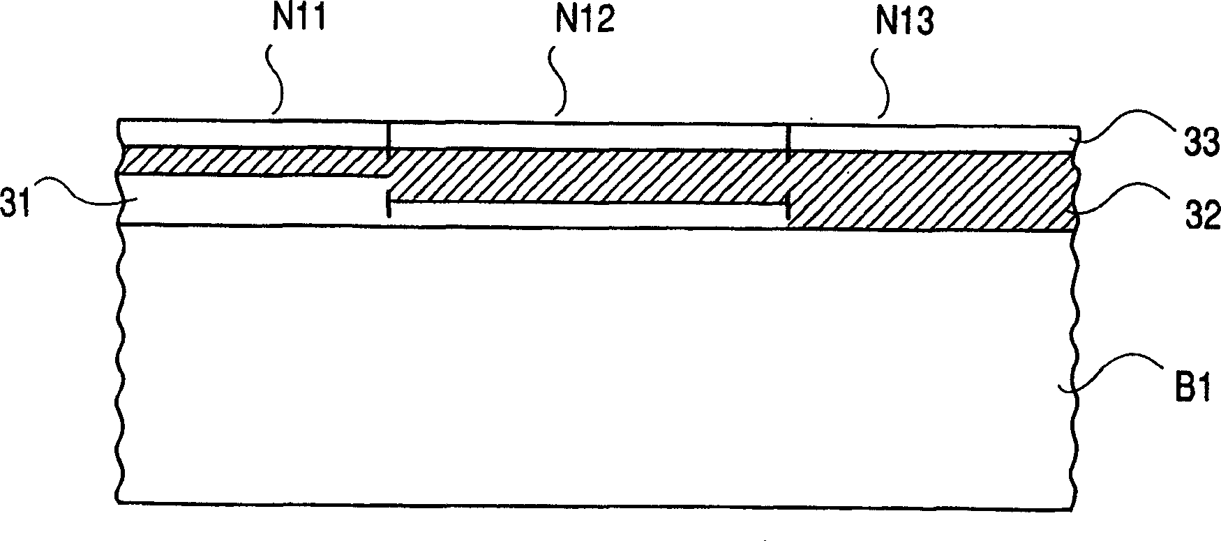
[0122] In the figure, S11 and S12 are diaphragm blades for forming the diaphragm opening, and the opening area can be changed by moving them relatively. P1 is an ND filter (filter member), pasted and fixed on the diaphragm blade S12. Therefore, as the diaphragm blades S11, S12 move relative to each other, the area where the ND filter P1 covers the opening changes. In addition, the ND filter P1 forms a region N13 with a small transmittance (concentration) on the substrate B1, a region N12 with the second smallest transmittance (medium transmittance), and a transmittance area N12 on the substrate B1 seque...

Embodiment 2

[0134]Embodiment 2 of the present invention is shown in FIG. 4A, FIG. 4B, FIG. 4C, and FIG. 4D. Fig. 4A, Fig. 4B, Fig. 4C, and Fig. 4D are embodiments in which the light quantity adjusting device (diaphragm device) of the present invention is applied in the same manner as in Embodiment 1, but different from Embodiment 1, the diaphragm blades and the ND are independently driven. Example of a filter, a device for adjusting the amount of light.

[0135] In the figure, S11 and S12 are diaphragm blades for forming the diaphragm opening, and the opening area can be changed by moving them relatively. P2 is an ND filter, and the diaphragm blades S11 and S12 can be driven independently. In this embodiment, from the open state shown in FIG. 4A to the predetermined narrowed state shown in FIG. 4B, the aperture is narrowed by the diaphragm blades S21 and S22 to adjust the amount of light, and then the aperture area is fixed, as shown in FIG. 4C. The ND filter P2 is inserted into the ope...

Embodiment 3

[0143] Embodiment 3 of the present invention is shown in Fig. 7A, Fig. 7B and Fig. 7C. 7A , 7B, and 7C are examples in which the light quantity adjustment device (diaphragm device) of the present invention is applied in the same manner as in the first embodiment. FIG. 7A shows an open aperture state, FIG. 7B shows an intermediate aperture state, FIG. 7C shows a minimum aperture state, and FIG. 7D shows a side view of FIG. 7A .

[0144] In the figure, S31 and S32 are diaphragm blades for forming the diaphragm opening, and the opening area can be changed by relatively moving them. P3 is an ND filter (filter member), pasted and fixed on the diaphragm blade S32. Therefore, as the diaphragm blades S31, S32 move relative to each other, the area where the ND filter P3 covers the opening changes.

[0145] Further, in the ND filter P3, a region N31 having a predetermined transmittance is formed on one surface of the substrate B3, and a region N32 having a different transmittance from...


PUM


Abstract

An optical performance is deteriorated by a minute phase difference of transmission wave front of an ND filter. In a light quantity adjusting device which includes an ND filter (P1) for attenuating a quantity of light passing through an aperture formed by diaphragm blades (S11 and S12) and in which a cover ratio of the aperture by the ND filter (P1) is changed, setting is conducted such that a phase difference between lights with a predetermined wavelength lambd which pass through regions (N11, N12, and N13) of the ND filter (P1) with different transmittances inside the aperture becomes substantially 0lambd, substantially 1lambd, or substantially 2lambd in a state in which the aperture is completely covered with the ND filter (P1).

Description

technical field [0001] The present invention relates to a light quantity adjusting device suitable for use in photographing devices such as video cameras and digital still cameras, and relates to a technology capable of suppressing deterioration of optical performance even for an imaging element with a small pixel pitch. Background technique [0002] In an imaging optical system of an imaging device such as a video camera, a light amount adjusting device that adjusts the amount of light by changing an aperture formed by a plurality of diaphragm blades is used. In such an aperture device, when the aperture is too small, a decrease in optical performance due to light diffraction becomes a problem. [0003] Therefore, there has been proposed and put into practical use a light quantity adjustment device which uses both aperture blades and an ND (neutral) filter, and whose aperture is not too small even under bright scene conditions. [0004] Japanese Patent Publication No. 2592...

Claims


Application Information

Patent Timeline
Patent Type & Authority Applications(China)
IPC IPC(8): G02B5/00G02B5/20G03B9/02H04N5/225H04N5/238
CPCH04N5/2254H04N5/238G02B5/005G02B5/205H04N23/75G03B9/02
Inventor 村田安规小山刚史
Owner CANON KK
Why Eureka
Try Eureka