
Radiating fin and fin assembly

A technology for heat dissipation fins and components, applied in electrical components, electrical solid devices, semiconductor devices, etc., can solve the problems of increased contact thermal resistance between heat dissipation fins and substrates, difficulty in controlling the stability of welding media, and affecting welding quality. The effect of maintaining stability, reducing contact thermal resistance, and improving soldering quality

Inactive Publication Date: 2005-01-19
DELTA ELECTRONICS INC
View PDF0 Cites 4 Cited by
  • Summary
  • Abstract
  • Description
  • Claims
  • Application Information

AI Technical Summary

Problems solved by technology

detailed as Figure 1C As shown, in the existing method of combining heat dissipation fins 102 by soldering, because the welding portions 102b of each heat dissipation fin 102 are closely adjacent to each other, the flux 106 in the solder under the welding portion 102b will be affected by the adjacent fins. (A-A surface as shown in the figure) is blocked and cannot escape, but can only flow out in a small amount from the shorter side of the welding part 102b, resulting in a large amount of flux 106 still remaining in the fin welding part 102b and the substrate 104 after welding. The welding surface between them makes it difficult to control the stability of the welding medium, which not only affects the welding quality but also significantly increases the contact thermal resistance between the cooling fins and the substrate

Method used


Image

  • Radiating fin and fin assembly
  • Radiating fin and fin assembly
  • Radiating fin and fin assembly

Examples


Embodiment Construction

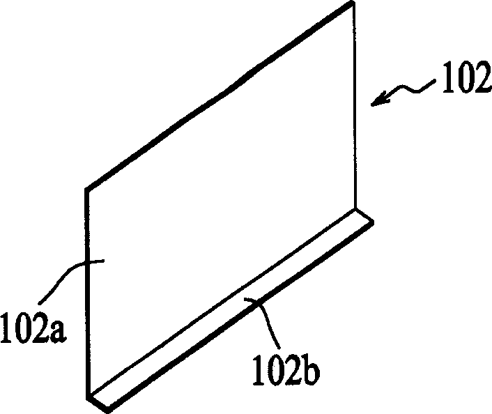
[0018] FIG. 2A is a perspective view showing the structure of the heat dissipation fin 12 according to an embodiment of the present invention.

[0019] As shown in FIG. 2A , the heat dissipation fins 12 are formed by bending a sheet of heat-conducting material into an L-shaped cross-section, and include a large-area heat dissipation portion 12 a and an elongated welding portion 12 b. The sheet-shaped heat-conducting material can be bent to form the welding portion 12b by means of sheet metal processing, and the heat-conducting material can be a high-heat-conducting material composed of aluminum, copper, aluminum alloy, copper alloy, or a mixture thereof.

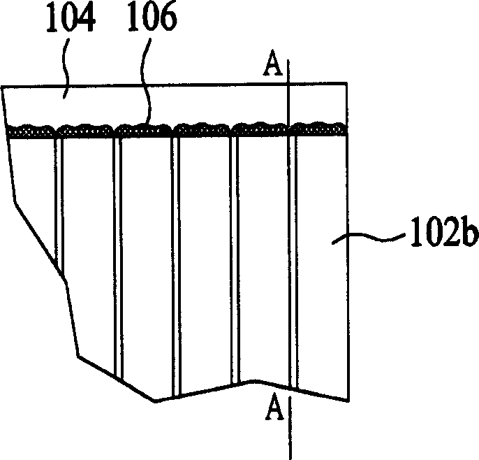
[0020] According to the design of the present invention, the welding portion 12b has a plurality of notches 14 formed by the edge of the sheet-shaped heat-conducting material inwardly toward the bend. The shape of the notches 14 can be in any form, and the number is not limited, so that The welding portion 12b has a serrated...


PUM


Abstract

The invention provides a cooling fin and fin component, where the former is composed of a sheet heat conduction material formed with notches, and the part of the material is bent to form a welding part for welding to a substrate; the latter is composed of a base slice and many cooling fins. The structures of the cooling fin and fin component can retain the stability of welding medium between the cooling fin and the substrate, thus able to improve the welding quality and effectively reduce contact thermal resistance between the cooling fin and the substrate.

Description

technical field [0001] The invention provides a cooling fin and a fin assembly, in particular a fin and a fin assembly which can effectively maintain the stability of a welding medium during welding and assembly. Background technique [0002] Today's heat dissipation fins are mostly manufactured by aluminum extrusion. However, the ratio of height to thickness of heat dissipation fins manufactured by aluminum extrusion process will be limited by the current processing technology, and the heat dissipation performance cannot be further improved, so it is difficult to meet Today's electronic components have greatly increased heat dissipation requirements. Therefore, it can be considered to be replaced by welding assembly. [0003] Figure 1A It is a three-dimensional view showing the structure of a conventional heat dissipation fin 102 used in a soldering process. Such as Figure 1A As shown, the cooling fins 102 are formed by bending a sheet of heat-conducting material into a...

Claims


Application Information

Patent Timeline
IPC IPC(8): H01L23/367
Inventor 简兆南施荣松吴玮芳陈锦明
Owner DELTA ELECTRONICS INC
Learn More