Micro power consumption reciprocating apparatus

A reciprocating device, micro power consumption technology, applied in electromechanical devices, magnetic objects, electrical components, etc., can solve the problems of unstable operation, reduced service life, unreliable operation, etc., to achieve fast fluid response time, prolong service life, The effect of prolonging the electrical life

Inactive Publication Date: 2005-01-19
刘文华 +1
View PDF0 Cites 9 Cited by
  • Summary
  • Abstract
  • Description
  • Claims
  • Application Information

AI Technical Summary

Problems solved by technology

[0002] At present, low-voltage electrical products such as solenoid valves, relays, protectors, and contactors used by people all follow the working principle of more than 100 years, that is, to continuously supply power to the coil, and the electromagnetic field generated makes the electromagnet and the moving iron core Pull in after overcoming the resistance of the spring, so that the solenoid valve products or low-voltage electrical products enter the working state. When the power is cut off, the electromagnetic field disappears, and the spring releases energy to achieve the purpose of shutting off. In order to achieve stable operation, the current must be increased to the coil input, which causes the coil to heat up, or even burn out, resulting in a decrease in service life. When the grid voltage changes, the voltage is too high, causing the coil to burn easily, and the voltage drops, directly causing unstable, jittering, and unreliable work. , and it will also cause the contacts of low-voltage electrical products to arc and burn out, and the fluid flow loss of solenoid valve products will be serious, causing difficulties for the system to fail to work. The working principle is caused by the passive working principle. Even if the voltage is stable, the coil will work for a long time, the temperature will rise, the resistance value will change, and the electromagnetic field will also change. Not only will the coil burn out, the work will be unstable, and noise and electromagnetic pollution will also be generated. Therefore, all kinds of disadvantages caused by the traditional working principle are caused by the basic working principle, which is inevitable.

Method used


Image

  • Micro power consumption reciprocating apparatus
  • Micro power consumption reciprocating apparatus
  • Micro power consumption reciprocating apparatus

Examples


Embodiment Construction

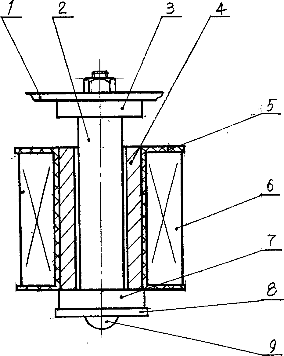
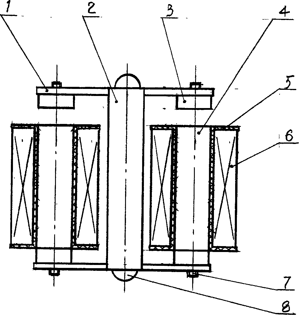
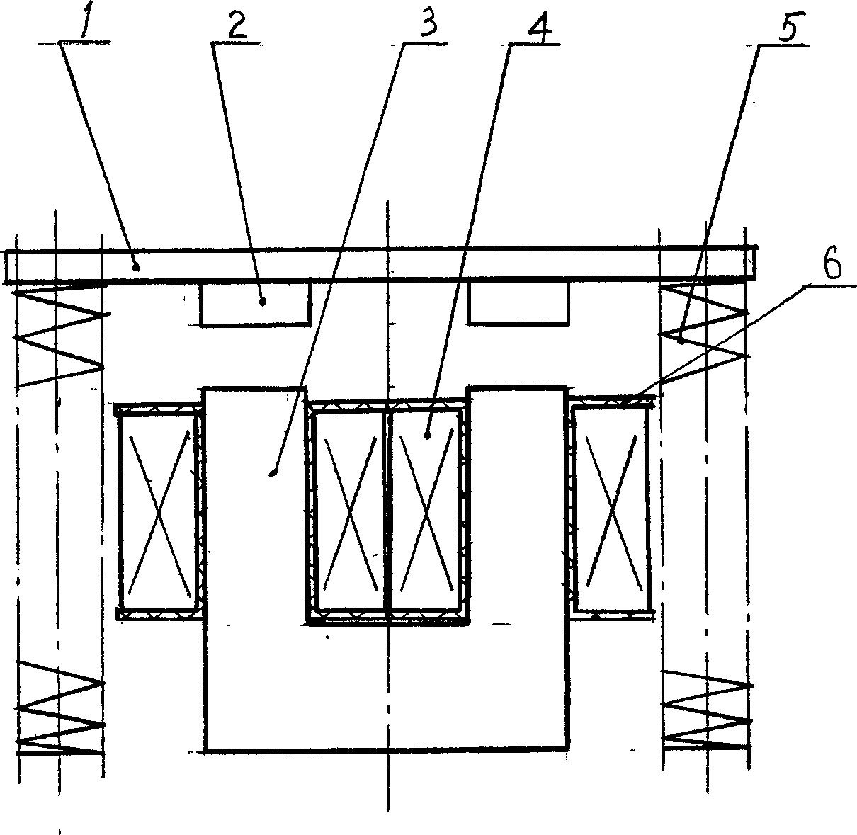
[0043] The purpose of the present invention is achieved in the following ways:

[0044] The device is equipped with a coil, wound on the coil bobbin. The coil bobbin is equipped with a ring-shaped soft iron core. The two ends of the ring-shaped soft iron core are installed along the central axis. The outer side of the coil bobbin is provided with permanent magnets with opposite polarities. The upper structure plate 6 and the pad iron 1 are fixed by bolts on the outer side of the permanent magnet; two sets of coils are wound on the coil frame, and the coil frame is equipped with soft iron cores, which are arranged on both sides of the bracket. The permanent magnets are arranged The two ends of the soft iron core have opposite polarities and are fixed on the end plate and bolted to the bracket to form an I-shaped motion frame; the permanent magnet is correspondingly installed on the end plate on the upper end of the U-shaped soft iron core. The coil The outside of the bobbin is inst...


PUM


Abstract

The invention is a micro-consumption reciprocator, provided with coil, the framework of the coils holds an annular soft iron core, there are permanent magnets arranged on two ends of the soft iron core, the magnet poles are opposite and connected by a post, and top structural plate and parallel are installed on two ends and fixed by bolts; as it applies a pulse current on the coil, the generated polarities and the polarities of the permanent magnets form the condition that the same polarities are mutually repulsive and the different polarities are mutually attractive and then bring about reciprocating motion, and it does not use the current to maintain the work, and can not make the coil heated and burnt, realizing the advantages of high electricity saving, reliable action, stability, simplicity, no noise, etc; it is used in electromagnetic valves, relays, breakers, protectors, contactors, and other switch products to form various series of independent products widely applied in industry, agriculture, national defence and spaceflight&aviation. It is used in lock products, able to interface with monitoring system and intelligentize, and able to be widely applied to civil houses, automobiles, housing estate management and safety departments.

Description

Technical field [0001] The invention relates to a power device that organically combines an electromagnetic field and a permanent magnet, thereby realizing mechanical reciprocating motion. Background technique [0002] At present, the solenoid valves, relays, protectors, contactors and other low-voltage electrical products used by people all follow the working principle of more than one hundred years, that is, continuous power supply to the coil, and the electromagnetic field generated makes the electromagnet and the moving iron core After the resistance of the spring is overcome, the solenoid valve products or low-voltage electrical products enter the working state. When the power is cut off, the electromagnetic field disappears and the spring releases energy to achieve the purpose of shutting off. In order to achieve stable work, the current must be increased to the coil This causes the coil to heat up or even burn down, resulting in a decrease in service life. When the network...

Claims


Application Information

Patent Timeline
Patent Type & Authority Applications(China)
IPC IPC(8): H01F7/122H01F7/16
CPCH01F7/122H01F7/1646H01F7/1615
Inventor 刘文华关利强
Owner 刘文华
Why Eureka
Try Eureka