Organic electroluminescent panel device

An electroluminescent, organic technology, applied in the field of organic electroluminescent panel devices, can solve the problems of waste, unsightly space configuration, and inability to reduce the number of electrodes, etc.

Inactive Publication Date: 2005-01-19
RITDISPLAY
View PDF0 Cites 1 Cited by
  • Summary
  • Abstract
  • Description
  • Claims
  • Application Information

AI Technical Summary

Problems solved by technology

Such a layout configuration, because the leads are only located on one side of the panel, forms an asymmetric configuration, resulting in unsightly or wasteful space configuration, and the configuration is concentrated on one side, which is inconvenient for assembly
And when the resolution of the display area needs to be improved, the width of the guide line region (X-Y lead region) often needs to be widened when the number of electrodes or the guide lines cannot be reduced, resulting in a large space occupation of the display device during application. shortcoming

Method used


Image

  • Organic electroluminescent panel device
  • Organic electroluminescent panel device
  • Organic electroluminescent panel device

Examples


Embodiment Construction

[0043] In order to further illustrate the structure, characteristics and purpose of the present invention, drawings and a detailed description of preferred specific embodiments are attached as follows;

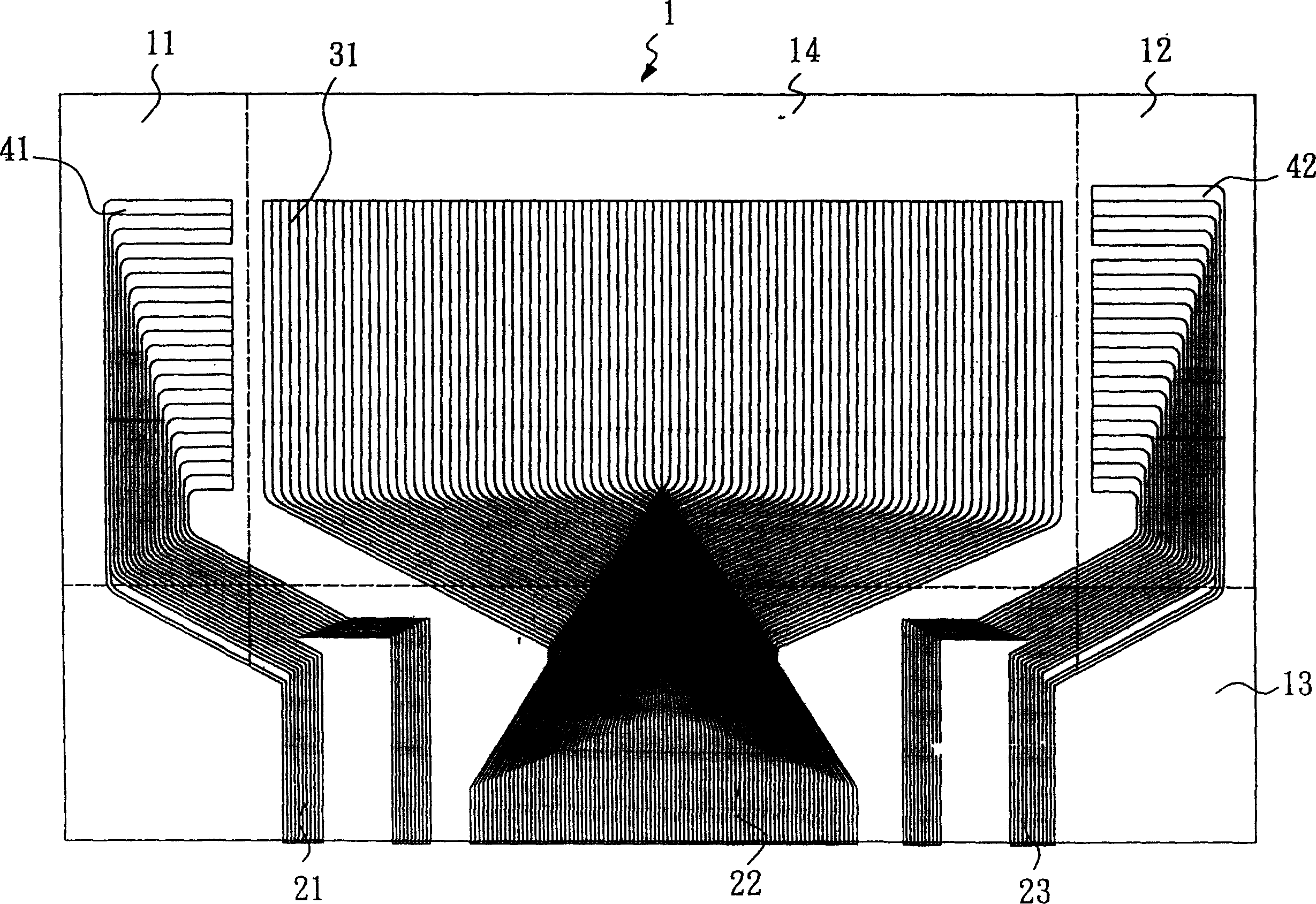
[0044] For preferred embodiments of the present invention, please refer to figure 1 A schematic diagram showing the wiring of an organic electroluminescent panel is mainly laid out on a substrate 1 . The substrate 1 is divided into a first wiring area 11 , a second wiring area 12 , a connecting wiring area 13 , and a display area 14 . In this embodiment, the material of the substrate 1 is not limited, and may be any known substrate, preferably a glass substrate.

[0045]The display area 14 of the organic electroluminescent panel substrate of this preferred embodiment is located between the first lead area 11 and the second lead area 12 . The connection lead area 13 is located below the first lead area 11 , the second lead area 12 , and the display area 14 . On the first wir...


PUM


Abstract

The invention relates to an organic electric-promoted light-emitting panel. It divides a base plate into the first leading wire area, the second leading wire area, connection leading wire area and display area. The display area distributes several first electrodes, several secondary electrode and organic light emitting function layer. Several first connection leading wire and several secondary leading wire is distributed in the first leading wire area and the second leading area. Several connection wires are distributed in connection leading wire area. The secondary electrode and the first leading wire or the second leading wire can connect to the control integrate circuit by connection wire.

Description

technical field [0001] The invention relates to a panel device, in particular to an organic electroluminescent panel device using organic materials as light emitting units. Background technique [0002] Organic electroluminescent displays (OLEDs) are currently one of the most promising flat panel display devices. The light-emitting unit used in the organic electroluminescent display (OLED) is quite different from the liquid crystal display technology that used liquid crystal as the optical switch medium in the past. The pixel light-emitting unit of the OLED will emit light by itself when the current is turned on and conducted, while the LCD or TFT- The panel of the LCD still needs an additional backlight module as the light source provided. [0003] Therefore, how to utilize the characteristics of the organic electroluminescent material itself to improve the space utilization flexibility of the OLED panel and to have a beautiful layout has become an important issue that the...

Claims


Application Information

Patent Timeline
IPC IPC(8): G09F9/30H05B33/12
Inventor 张毅卢添荣吴清辉
Owner RITDISPLAY
Why Eureka
Try Eureka