Motor control unit

A motor control and control device technology, applied in the control system, AC motor control, motor control in four quadrants, etc., can solve the problems of not being able to increase the torque, increase the torque, etc., and achieve the effect of increasing the output torque

Inactive Publication Date: 2005-02-02
FANUC LTD
View PDF2 Cites 4 Cited by
  • Summary
  • Abstract
  • Description
  • Claims
  • Application Information

AI Technical Summary

Problems solved by technology

[0004] In the invention described in the above-mentioned patent documents, the voltage utilization efficiency is improved by superimposing a voltage three times the frequency of the basic sine wave on the basic sine wave voltage as a voltage command for each phase. However, the current flowing in each phase is Sine wave, the maximum current value is the peak value of the sine wave, and the torque cannot be increased except for increasing the peak value, that is, the amplitude

Method used


Image

  • Motor control unit
  • Motor control unit
  • Motor control unit

Examples


Embodiment Construction

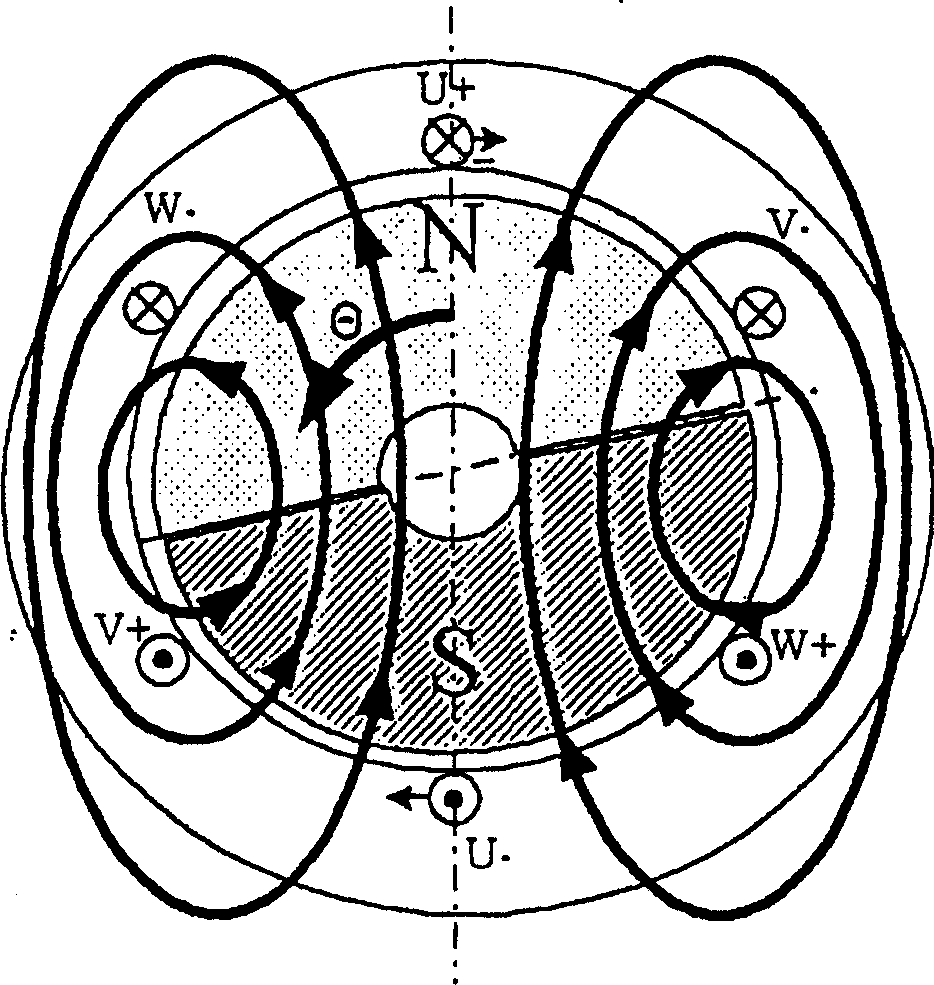
[0016] figure 1 , is an explanatory diagram of the operation principle when the present invention is applied to a synchronous motor using permanent magnets.

[0017] exist figure 1 Among them, U+, U-, V+, V-, W+, W- are the stator coils of U, V, and W phases, and N, S represent the magnetic poles of the rotor

[0018] Assuming that the U-phase coil is connected to Θ, the strength of the magnet is M, and the interlinked magnetic flux φU in the U-phase coil is expressed by

[0019] φU=M·sinΘ

[0020] express.

[0021] Similarly, the interlinked magnetic flux φV, φW in the V and W phase coils is expressed as:

[0022] φV=M sin(θ+2 / 3π)

[0023] φW=M sin(θ+4 / 3π)

[0024] In order to generate a certain torque by flowing current in the U, V, and W phase coils with such a magnetic flux distribution, the current flowing in each phase coil is:

[0025] IU=I·sinθ

[0026] IV=I·sin(θ+2 / 3π)

[0027] IW=I·sin(θ+4 / 3π)

[0028] The moment that occurs at this time is:

[0029] Gener...


PUM


Abstract

Windings of each phase in a three-phase AC motor are independent of one another. A motor control unit gives, to windings of each phase (U, V and W-phase), currents (IU, IV, IW) obtained by adding, to a fundamental sine wave current, a current having a frequency which is three times as high as that of the fundamental sine wave current. That is, IU=Isin(Omegat)+Ia.sin(3Omegat); IV=Isin(Omegat+2 / 3pi )+Iasin(3Omegat); IW=Isin(Omegat+4 / 3pi)+Iasin(3Omegat). Also, amplitude (Ia) of a current having a frequency which is three times as high as that of the fundamental sine wave current is set to a predetermined value smaller than amplitude (I) of the fundamental sine wave current.

Description

technical field [0001] The present invention relates to a control device for a 3-phase AC motor. Background technique [0002] Conventionally, in a three-phase AC motor, a sine wave current of a fundamental frequency flows through each phase to drive the motor. The maximum torque that the motor can output is determined by the peak current value of the sine wave current flowing in each phase, that is, the magnitude of the amplitude. [0003] In order to improve the efficiency of voltage utilization, the well-known control method is: superimpose the voltage command of 3 times the basic frequency on the voltage command of the basic frequency sent to each phase as the voltage command, and make it into a PWM signal to drive the inverter (see Special Kaiping No. 6-133558, JP-11-69899). [0004] In the invention described in the above-mentioned patent documents, the voltage utilization efficiency is improved by superimposing a voltage three times the frequency of the basic sine w...

Claims


Application Information

Patent Timeline
Patent Type & Authority Applications(China)
IPC IPC(8): H02M7/48H02P6/06H02P6/08H02P23/07H02P27/06H02P27/08
CPCH02P27/06
Inventor 坂本启二前田尚志
Owner FANUC LTD
Why Eureka
Try Eureka