Integrated borehole system for reservoir detection and monitoring

A technology of wellbore and measurement value, which is applied in the field of integrated well system for exploration and monitoring of oil and gas reservoirs, and can solve problems such as resolution reduction.

Inactive Publication Date: 2005-02-02
KJT ENTPR
View PDF8 Cites 5 Cited by
  • Summary
  • Abstract
  • Description
  • Claims
  • Application Information

AI Technical Summary

Problems solved by technology

The resolution is therefore reduced accordingly

Method used


Image

  • Integrated borehole system for reservoir detection and monitoring
  • Integrated borehole system for reservoir detection and monitoring
  • Integrated borehole system for reservoir detection and monitoring

Examples


no. 1 example

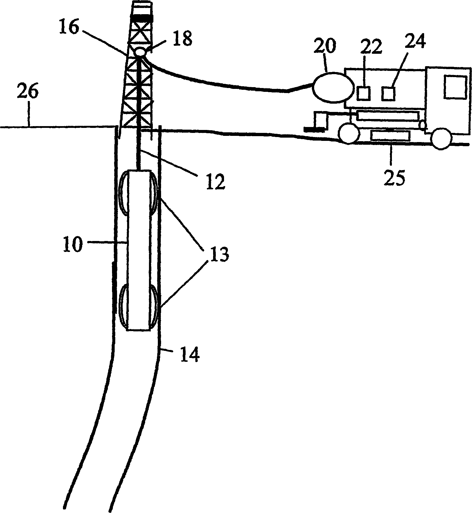
[0026] The present invention discloses a system for generating an image of a subsurface formation around a wellbore. According to the first example of the present invention, an open hole logging tool system is used to measure formation resistivity with direct current signal, formation conductivity and resistivity electromagnetic measurement, and seismic wave velocity measurement. A preliminary well image, referred to herein as a "pseudo-section", is generated from the DC signal measurements of formation resistivity. Formation resistivity and conductivity values ​​derived from electromagnetic measurements can then be used to further improve the downhole image described by the "pseudo-section". The surface seismic data can then also be constrained using the existing subsurface velocity profile of the seismic waves, together with the subsurface image generated from the DC signal measurements of formation resistivity, electromagnetic resistivity, and conductivity measurements. Ac...


PUM


Abstract

A method is disclosed for generating an image of earth formations penetrated by a wellbore. The method includes generating an initial model of the earth formations using formation resistivity measured by a direct current signal. A response to the initial model of an instrument used to make the direct current resistivity measurements is calculated. The calculated response is compared to the measurements of resistivity. The model is adjusted, and the calculating and comparing are repeated until a difference between the calculated response and measurements reaches a minimum. The adjusted model is refined based on resistivity measurements made using an electromagnetic measuring instrument, and the refined model is constrained using acoustic velocity measurements.

Description

technical field [0001] The present invention is a device and a related method for imaging formation rocks around boreholes. Background technique [0002] Energy exploration and development uses drilling to access formations within the Earth, while monitoring and evaluating various physical parameters of the formation rock, such as the resistivity and electrical conductivity of the formation around the wellbore. [0003] The methods of electromagnetic field excitation can be roughly divided into frequency domain excitation and time domain excitation. In frequency domain excitation, a continuous wave signal is usually transmitted at a fixed frequency, but the transmitted signal can be multiple superimposed frequencies. For time-domain excitation, it is necessary to switch the signal abruptly, where the signal can be a square wave or a pulse, a triangle wave or a pseudo-random binary sequence signal. [0004] A limitation of frequency domain (continuous wave) excitation is th...

Claims


Application Information

Patent Timeline
Patent Type & Authority Applications(China)
IPC IPC(8): G01V11/00
CPCG01V11/00G01V2210/6163G01V3/20G01V3/22G01V3/28G01V3/38
Inventor 库尔特·马丁·斯泰克
Owner KJT ENTPR
Why Eureka
Try Eureka