LED control apparatus

A technology of light-emitting diodes and photosensitive diodes, applied in the field of RGB-based LED illuminants, can solve the problems of complex implementation and insufficient utilization

Inactive Publication Date: 2005-02-02
SIGNIFY HLDG BV
View PDF0 Cites 19 Cited by
  • Summary
  • Abstract
  • Description
  • Claims
  • Application Information

AI Technical Summary

Problems solved by technology

The implementation becomes complex due to the use of the PWM control and also does not fully utilize the LED

Method used


Image

  • LED control apparatus
  • LED control apparatus
  • LED control apparatus

Examples


Embodiment Construction

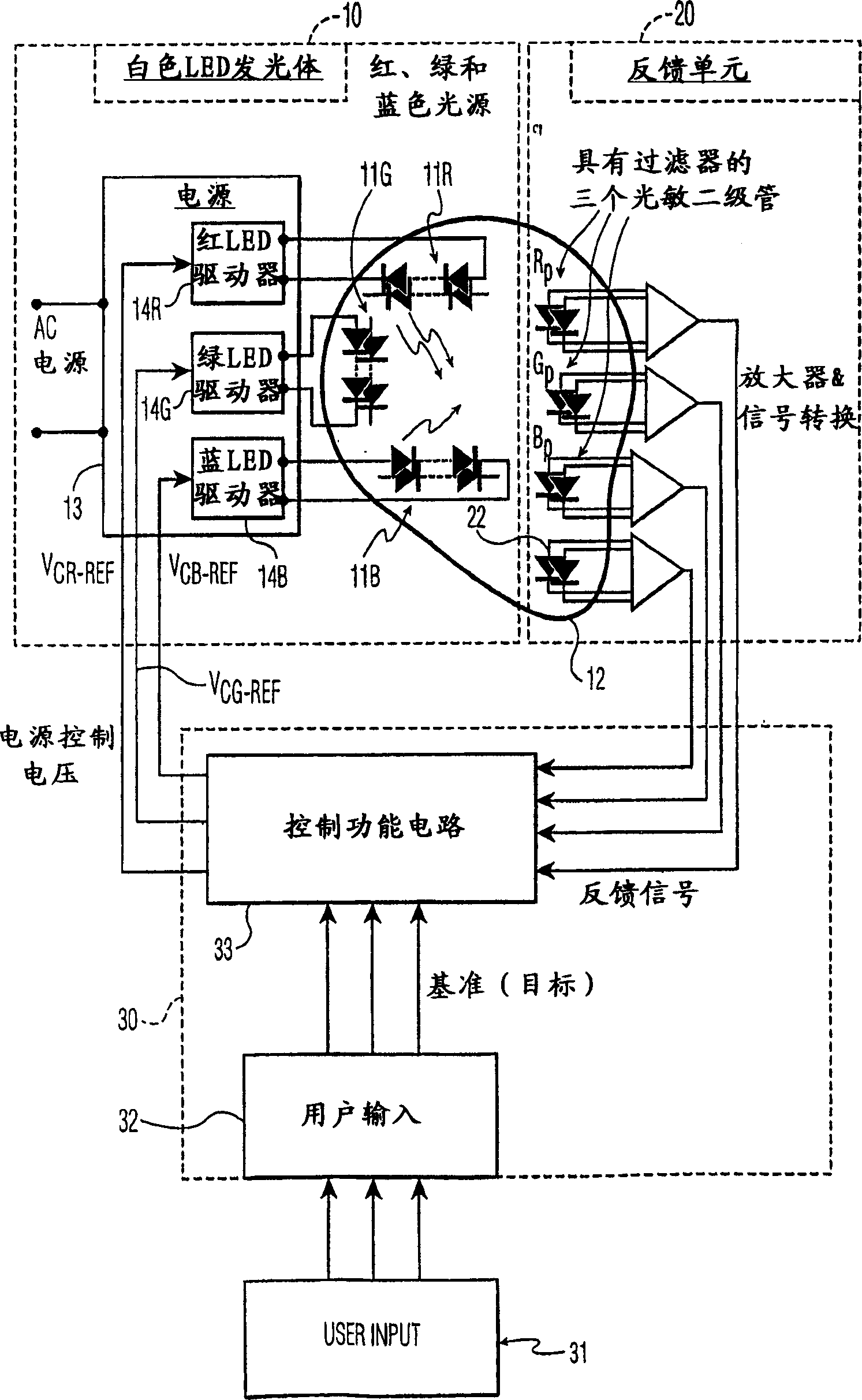
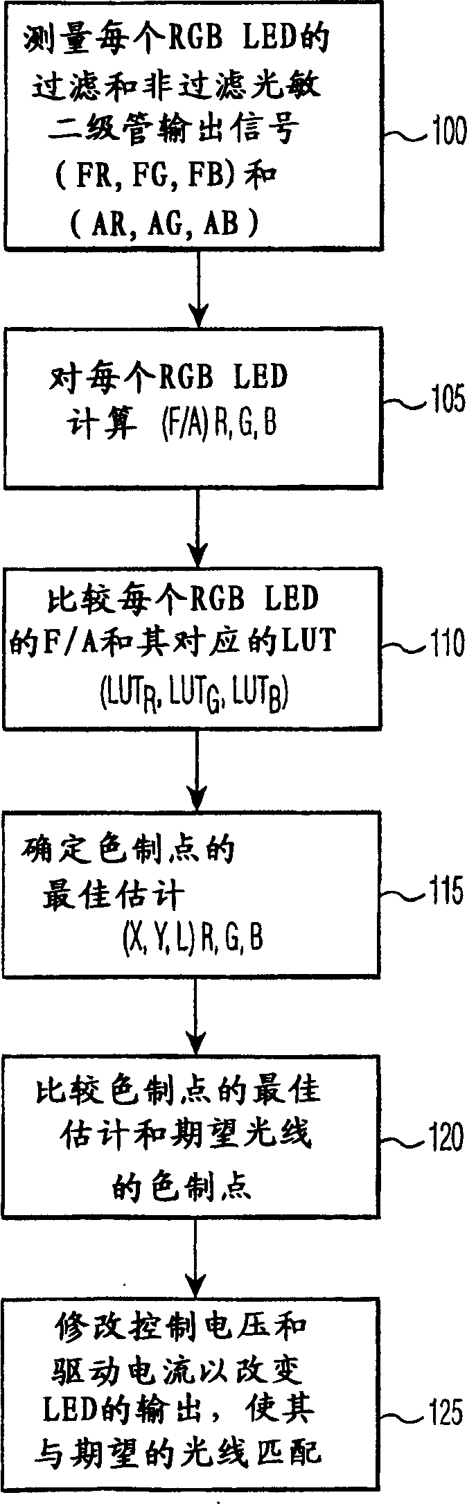
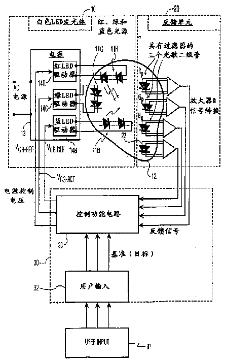
[0020] RGB LEDs can be used to generate white light. This is nothing new. The same principle is used in fluorescent tube lighting and televisions, both based on phosphor emission rather than LED emission. In the field of chromaticity, color is quantified by chromaticity coordinates, the most widely used of which is CIE (Commission Internationale de l’Eclairage) 1931 (x, y, L) chromaticity coordinates. Here the combination of x and y defines the color, and L defines the brightness of the light or luminosity. The system is based on the average observer's eye response and is an internationally accepted standard.

[0021] Consistent production of high quality white light relies primarily on having lamps with approximately the same chromaticity coordinates. In other words, it is important for the manufacturer of lamps that each lamp of a particular kind is visually identical to the user / observer. In the case of fluorescent tube lighting, this can be achieved by mixing phosphors...


PUM


Abstract

Method and apparatus for controlling an RBG based LED luminary which measures the output signals of filtered photodiodes and unfiltered photodiodes and correlates these values to chromaticity coordinates for each of the red, green and blue LEDs of the luminary. Forward currents driving the LED luminary are adjusted in accordance with differences between the chromaticity coordinates of each of the red, green and blue LEDs and chromaticity coordinates of a desired mixed color light.

Description

technical field [0001] The present invention relates to RGB-based LED illuminants, and more particularly, the present invention relates to apparatus for controlling RGB-based LED illuminants in which the The wavelength difference between the desired wavelengths is adjusted so that the LED light emitter produces the desired color and illuminance. Background technique [0002] As is well known in the art, light emitters based on red, green and blue (RGB) light emitting diodes (LEDs) produce light of different colors which, when properly mixed, produce white light. RGB LED-based illuminants are widely used in applications such as LCD backlighting, residential freezer lighting, and white lighting. Lighting with LED-based illuminants presents some difficulties because the optical properties of individual RGB LEDs vary with temperature, forward current, and aging. In addition, the characteristics of each batch of LEDs produced by the same LED production process are obviously dif...

Claims


Application Information

Patent Timeline
Patent Type & Authority Applications(China)
IPC IPC(8): H05B37/02G09G3/34H01L33/00H05B44/00
CPCG09G3/3406Y10S362/80H05B33/0869H05B45/22
Inventor F·J·P·舒尔曼斯
Owner SIGNIFY HLDG BV
Why Eureka
Try Eureka