Cervical spine fixator and screwdriver used therefor

A cervical spine fixation and fixator technology, applied in the field of cervical spine fixators, can solve the problems of increased production and manufacturing, thicker plate elements, and trouble.

Inactive Publication Date: 2005-02-09
U & I INC
View PDF2 Cites 11 Cited by
  • Summary
  • Abstract
  • Description
  • Claims
  • Application Information

AI Technical Summary

Problems solved by technology

[0011] However, there are still some disadvantages in WO 00 / 78238A1 and EP 1169971A2 in that fixing tools or split rings are accommodated in the holes of the plate elements by elastically deforming the elements under the action of pressure to fix the head of the screw so that the fixing operation process becomes more complicated. more difficult, adding more trouble to manufacturing, and resulting in thicker plate elements

Method used


Image

  • Cervical spine fixator and screwdriver used therefor
  • Cervical spine fixator and screwdriver used therefor
  • Cervical spine fixator and screwdriver used therefor

Examples


Embodiment approach

[0036] Preferred embodiments of the present invention will be described in detail below with reference to the accompanying drawings, wherein these embodiments do not limit the protection scope of the present invention, but are for reference purposes only.

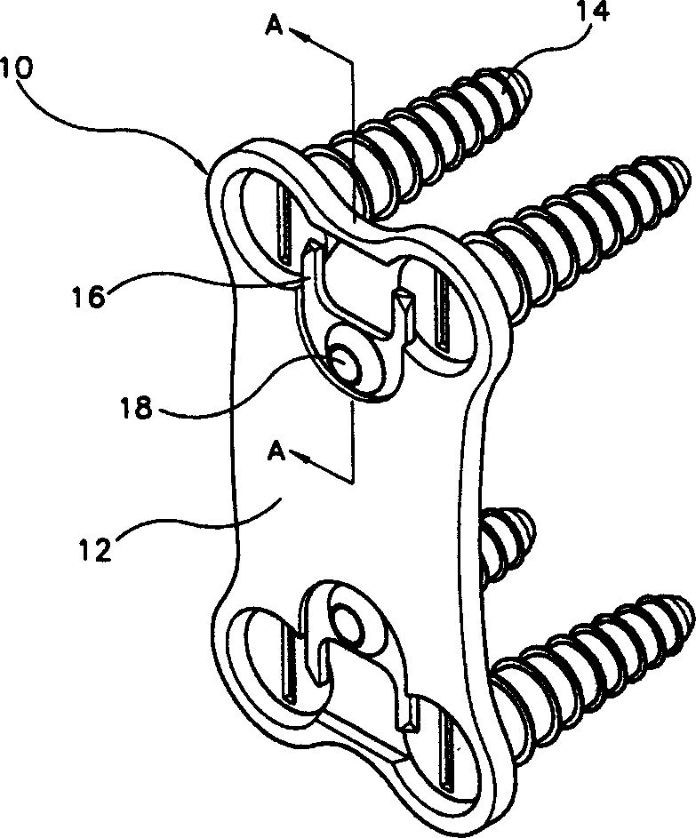
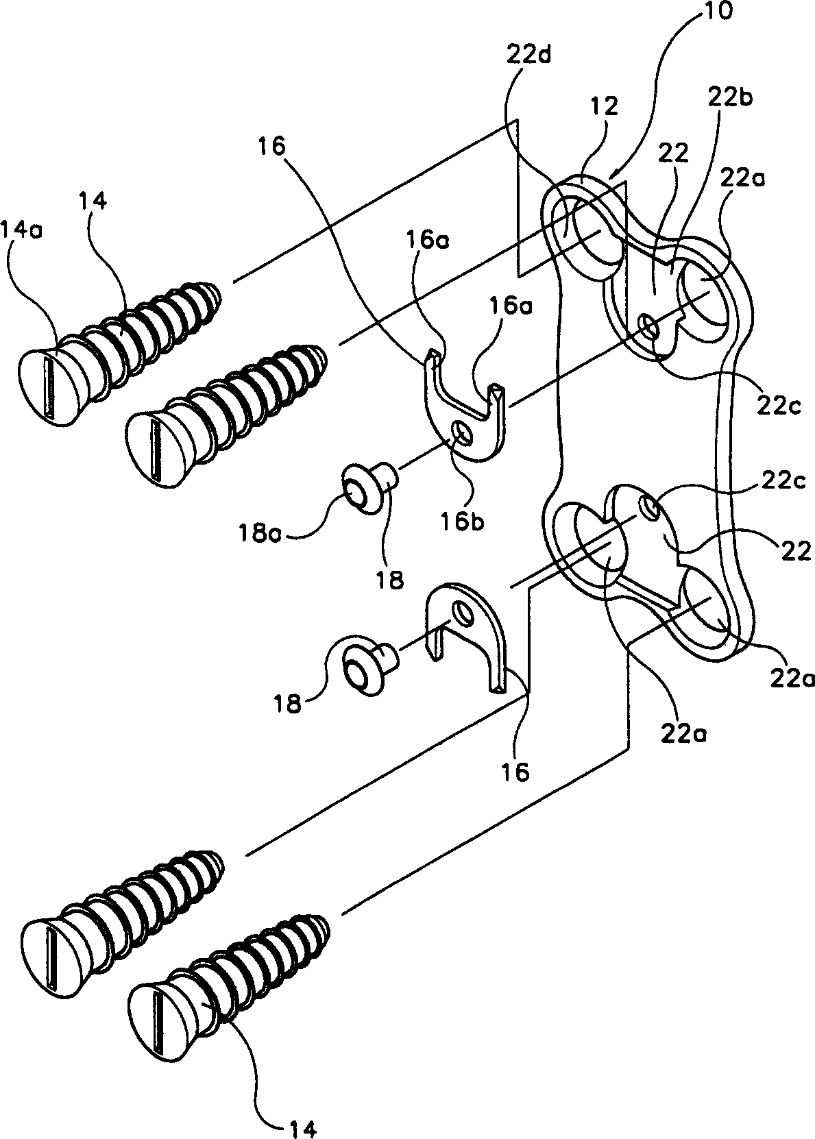
[0037] Such as figure 1 with figure 2 As shown, the cervical vertebra fixer 10 according to the first embodiment of the present invention includes a plate element 12 adjacent to the cervical vertebra fixation area, a plurality of screws connected to the plate element 12 and fastened to the cervical vertebra at the same time, and fixed on the plate element 12 is used to prevent screw head fixing element 16 from screwing out.

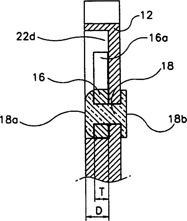
[0038] The screw head fixing element 16 is fixed on the plate element 12 by known connection methods such as riveting 18 or welding. Typically, the plate member 12 has a rectangular shape and is curved to match the curvature of the cervical spine. On the surface of the plate element 12 opposite to ...


PUM


Abstract

A cervical spine fixator and a screwdriver used therefore is disclosed wherein the fixator comprises plates (12, 212) for being adjoined to a cervical spine fixation region and a plurality of screws (14, 214). The plurality of screws are fixedly inserted into a patient's cervical spine and simultaneously coupled to the plates, wherein an adjacent region coupled with the screws in the plates is fixed with screw head fixture members (16, 216) having a protruder, which is deformed under the effect of pressure by a screw head when the screws are inserted and returns to their position of origin when the screw head is completely accommodated into the plates to be hitched by the screw head. The plates are formed thereon with receiving grooves (22, 222) for accommodating the screw head and the screw head fixture member. The receiving grooves are formed with openings into which the screws are inserted and a recess into which the screw head is received. The screw (214) formed with a groove of concaved curvature is installed or removed by a screwdriver (230) formed with a protruder of convex curvature, such that it is easy to manufacture, and the thickness of the plates is reduced, thus eliminating the feeling of a foreign substance after a surgical operation.

Description

technical field [0001] The present invention generally relates to a cervical spine fixator implanted as an anterior neck for the treatment and correction of cervical intervertebral disc disease, cervical herniated disc disease, cervical spondylotic myelopathy, cervical spondylosis, etc. Fractures, dislocations, tumors and mutations in the back of the neck and other diseases. Background technique [0002] Cervical misalignments are generally treated by maintaining an ideal spatial relationship and orientation of the individual cervical vertebrae relative to each other. A common neck fixation device includes a plate member and a fixation device comprising a plurality of screws fixedly insertable into the plate. [0003] The fixation device comprises fixation screws for pushing or fixing into the upper and lower cervical vertebrae of the cervical spine, whereby the individual vertebrae are fixed or handled by the locking force of the plate elements and the fixation screws. ...

Claims


Application Information

Patent Timeline
Patent Type & Authority Applications(China)
IPC IPC(8): A61B17/58A61B17/70A61B17/80A61B17/86A61B17/88A61F2/44
CPCA61B17/7059A61B17/8875A61B17/8042A61B17/86
Inventor 具滋教
Owner U & I INC
Why Eureka
Try Eureka