Lamps apparatus and front viewing lamp for vehicle

A technology for headlamps and lamps, applied in vehicle lighting systems, signal devices, lighting devices, etc., can solve problems such as difficulty in forming light and dark cut-off lines

Inactive Publication Date: 2005-02-09
KOITO MFG CO LTD
View PDF2 Cites 5 Cited by
  • Summary
  • Abstract
  • Description
  • Claims
  • Application Information

AI Technical Summary

Problems solved by technology

[0008] When the linear light source device described in Patent Document 2 is applied to vehicle headlights, it is possible to form a light distribution pattern with a cut-off line at the upper end due to the small lamp structure, but there is a problem in this case. : Difficulty forming a clear cut-off line

Method used


Image

  • Lamps apparatus and front viewing lamp for vehicle
  • Lamps apparatus and front viewing lamp for vehicle
  • Lamps apparatus and front viewing lamp for vehicle

Examples


Embodiment Construction

[0042] Hereinafter, embodiments of the invention of the present application will be described with reference to the drawings.

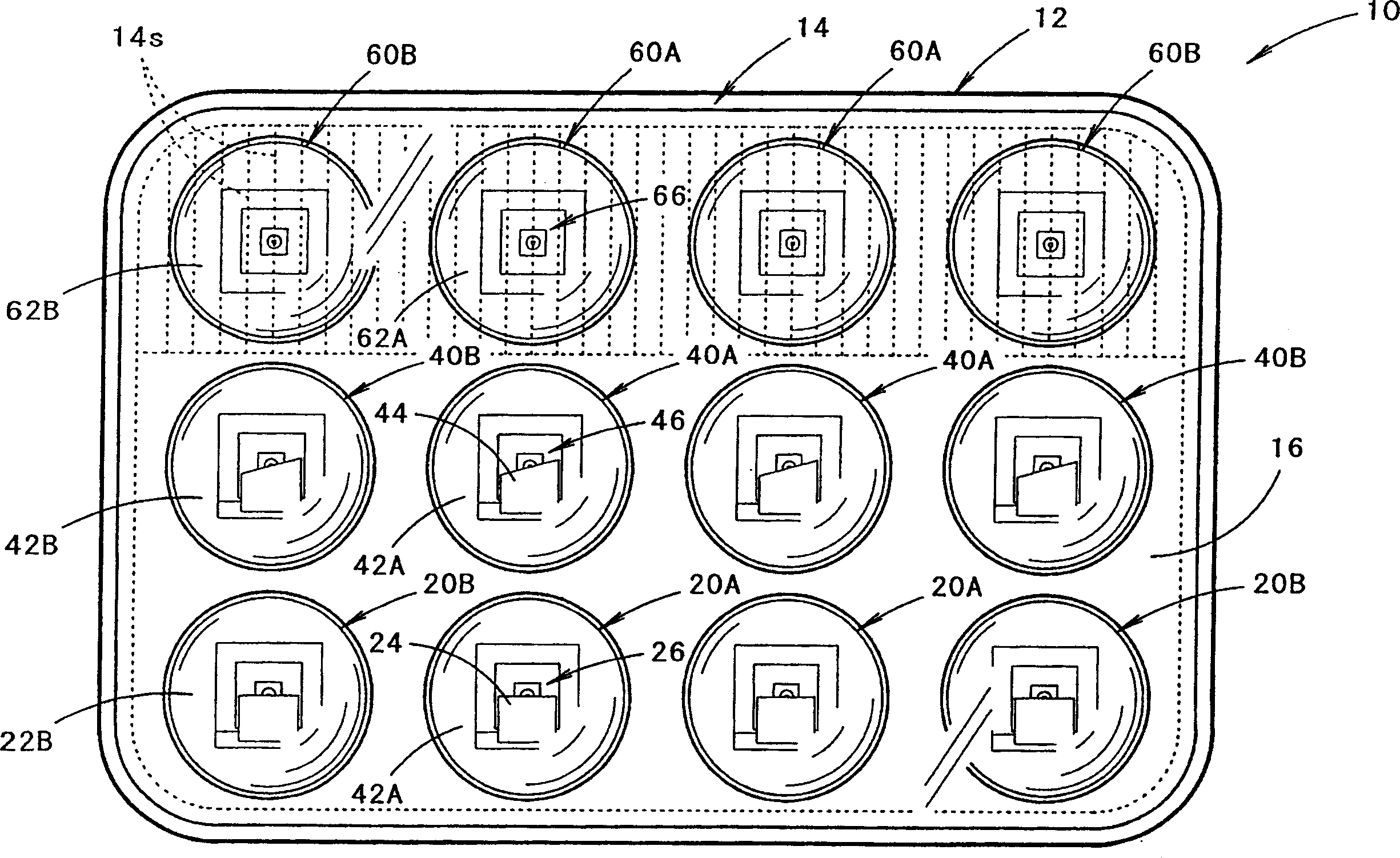
[0043] figure 1 It is a front view showing a vehicle headlamp according to an embodiment of the present invention.

[0044] As shown in the figure, the vehicle headlamp 10 according to this embodiment is configured by accommodating twelve lamp devices in three sections up and down in a lamp chamber formed by a lamp body 12 and a light-transmitting cover 14 mounted on the opening at the front end thereof. . That is, four lighting devices 20A, 20B are arranged in the lower stage, four lighting devices 40A, 40B are arranged in the middle stage, and four lighting devices 60A, 60B are arranged in the upper stage.

[0045] Most of the translucent cover 14 is transparent, but in the upper area, a plurality of diffusion lens elements 14s are formed in vertical stripes for horizontally diffusing the irradiation light from the four lighting devices 60A and 60...


PUM


Abstract

The lamp unit has a projection lens (22A) placed on an optic axis of a light emitting diode (26). A stopper unit (24) is placed at proximity of a rear focal point of the lens. An upper edge of the stopper unit is placed at proximity of the optical axis such that a lower part of the light emitted by the diode is stopped. The lens has a configuration for converging light from the diode towards the optical axis. - An INDEPENDENT CLAIM is also included for a headlight of a vehicle.

Description

technical field [0001] The present invention relates to a lighting device and the like used to form a cut-off line in a vehicle headlamp. Background technique [0002] Conventionally, as described in Patent Document 1, a light distribution pattern having a cut-off line at an upper end is formed by light irradiation from a plurality of lamp devices, and a vehicle headlamp configured in this manner is known. [0003] In addition, Patent Document 2 describes a linear light source device configured by arranging a plurality of light emitting diodes in a straight line so that light emitted from a linear light source is reflected forward by a predetermined reflection member. [0004] Patent Document 1 [0005] Japanese Patent Application Publication No. 2001-270383 [0006] Patent Document 2 [0007] Japanese Patent Application Publication No. 2003-31011 Contents of the invention [0008] When the linear light source device described in Patent Document 2 is applied to vehicle...

Claims


Application Information

Patent Timeline
Patent Type & Authority Applications(China)
IPC IPC(8): F21S8/12F21S8/10F21V5/00F21V11/16F21V13/00F21W101/10F21Y101/00F21Y101/02
CPCF21S48/1258F21S48/145F21S48/1154F21S48/1747F21Y2101/02F21Y2115/10F21S41/143F21S41/153F21S41/255F21S41/43F21S41/663
Inventor 塚本广德
Owner KOITO MFG CO LTD
Why Eureka
Try Eureka