Ground-support-free continous rigid frame bridge sidespan closure method

A technology of no landing, rigid frame bridge, applied in the field of bridge construction

Inactive Publication Date: 2005-02-16
北京建达道桥咨询有限公司
View PDF0 Cites 25 Cited by
  • Summary
  • Abstract
  • Description
  • Claims
  • Application Information

AI Technical Summary

Problems solved by technology

Therefore, the advantages of cantilever construction in previous construction schemes have been greatly discounted by the side-span cast-in-place method

Method used


Image

  • Ground-support-free continous rigid frame bridge sidespan closure method
  • Ground-support-free continous rigid frame bridge sidespan closure method
  • Ground-support-free continous rigid frame bridge sidespan closure method

Examples


Embodiment 1

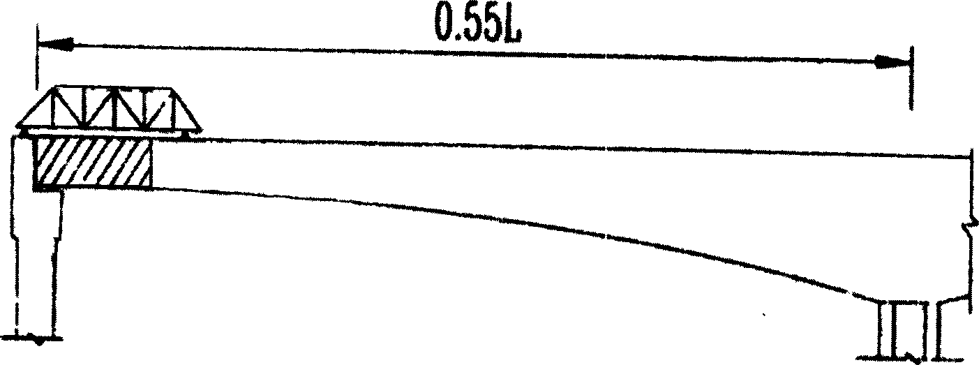
[0013] Such as Figure 1A , the original design is a continuous rigid frame bridge of 65+2×100+65m, which is closed with side spans and ground supports, and is now changed to 59+2×10⁶+59m, with a side span / middle span ratio of 0.557, which belongs to the side span The minimum side-span / middle-span ratio of the pier without negative reaction force is in the range of 0.54 to 0.56, and the length of the side-span closing section is 7m, which can be closed with hanging blue cast-in-place. The steps are:

[0014] Select the side span / middle span ratio as 0.557, lay out the span according to the hydrogeological conditions of the river, and draw up the section;

[0015] Use a mature analysis program for design and analysis, and select a suitable section when the side-span fulcrum has the positive and negative force of the fulcrum that meets the requirements of the technical specification under any load;

[0016] Arrange ordinary steel bars and prestressed bars according to the inte...

Embodiment 2

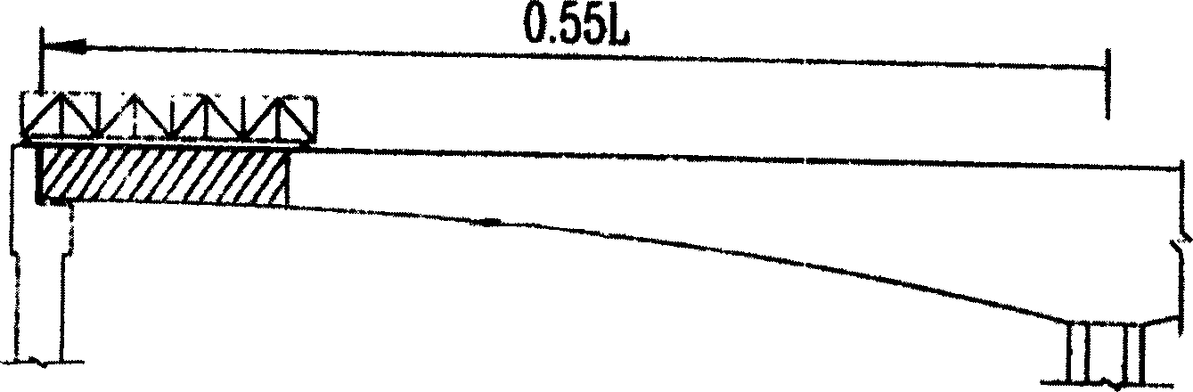
[0022] Such as Figure 1B , a bridge with a designed side span of 150m and a mid-span of 270m has a side-span / middle-span ratio of 0.556, which falls within the range of the minimum side-span / middle-span ratio of 0.54 to 0.56 for the side pier without negative reaction force. In this way, after the 16m side span closing section of the guide beam is cast in-situ, no matter where the live load is placed, there will be no negative reaction force at the fulcrum of the side pier and a certain reserve pressure will remain; 1 / 2 of the guide beam is applied to the cantilever And when the self-weight of the 16m cast-in-place section, the construction does not need additional cables, so that the guide beam method can be safely used to pour the cast-in-place box girder with a side span of 16m. Only when the foundation construction of the full hall support has been completed, the cast-in-place closure on the full hall support is used, such as: 14m is cast-in-situ on the support section, a...


PUM


Abstract

This invention relates to a side span closure method for a continuous rigid bridge without down-to-the-ground frames including selecting a ratio of side span/middle span in the sphere of 0.54-0.56, laying out and designing sections in terms of the river course hydrogeological condition, designing and analyzing it to select suitable sections to arrange ordinary steel bars and prestressed bars and drafting a construction pattern, symmetrically casting in terms of each T, selecting one way to finish side span closure: A the side span site-cast handing basket is extended and moves forward, the other end is supported on a side pier, utilizing the suspending arm and the side pier to bear the basket to site cast the closure section, B removing the basket and matching the truss beam on the beam and side pier an hanging forms.

Description

technical field [0001] The invention relates to a bridge construction method, in particular to a method for closing the side spans of a continuous rigid frame bridge without ground supports. Background technique [0002] For the continuous rigid frame bridges built in the past, the closure of the side spans is basically carried out by erecting supports and casting in-situ. Generally speaking, the ratio of the side span to the middle span is 0.6~0.67, which makes the cast-in-place section of the side span longer, often up to 22m, and has to be poured with floor-to-ceiling brackets. During the construction process, this process is very difficult, especially in the case of high piers, and the cost of materials is laborious. Such supports (such as bent frames) also have difficult water foundations in the water, and in windy areas, there are also wind stability problems. In addition to the large cost, it is not allowed on the navigable waterway or the flood discharge channel. ...

Claims


Application Information

Patent Timeline
Patent Type & Authority Applications(China)
IPC IPC(8): E01D21/00
Inventor 杨征宇吴洪峰张文桦
Owner 北京建达道桥咨询有限公司
Why Eureka
Try Eureka