Cast-in-place concrete shuttering member

A formwork component and cast-in-place concrete technology, which can be applied to building components, building structures, floor slabs, etc., can solve problems such as increasing construction costs and reducing construction speed.

Inactive Publication Date: 2005-02-16
湖南邱则有专利战略策划有限公司
View PDF4 Cites 2 Cited by
  • Summary
  • Abstract
  • Description
  • Claims
  • Application Information

AI Technical Summary

Problems solved by technology

However, after this polyhedral solid lightweight material member is applied to the cast-in-place concrete floor, it still needs to support the construction formwork, which reduces the construction speed and increases the construction cost. for urgent need

Method used


Image

  • Cast-in-place concrete shuttering member
  • Cast-in-place concrete shuttering member
  • Cast-in-place concrete shuttering member

Examples


Embodiment Construction

[0037] The present invention will be further described below in conjunction with the accompanying drawings and embodiments.

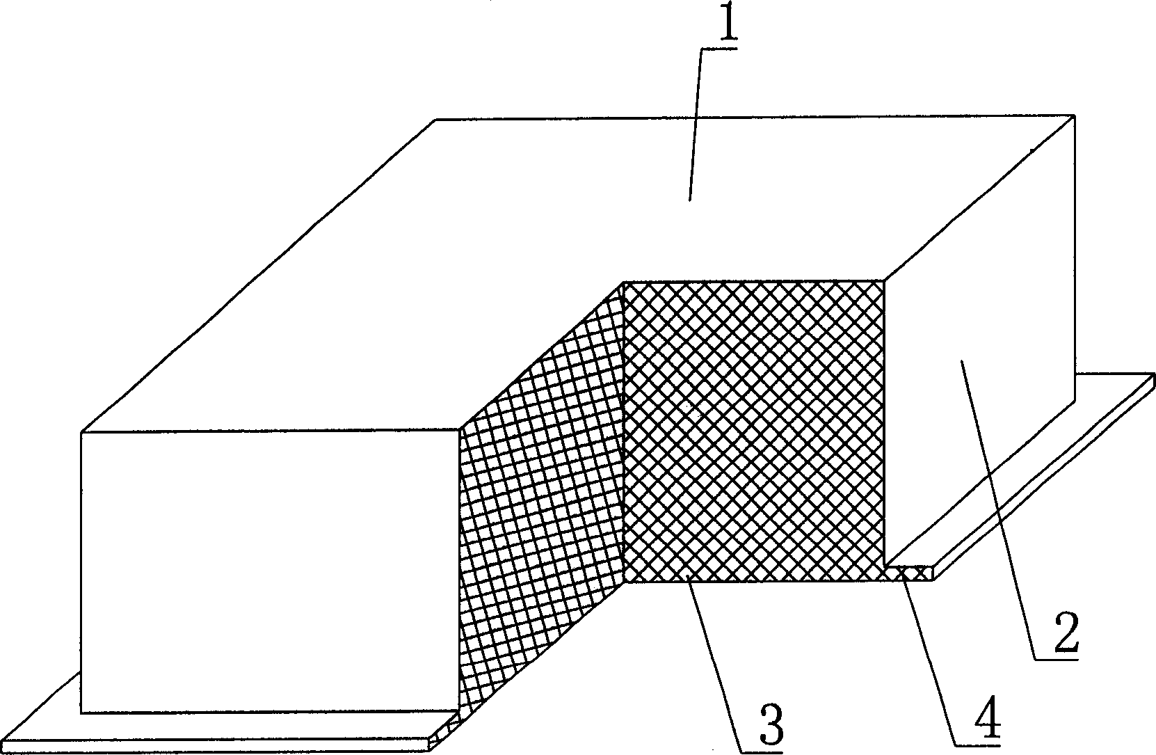
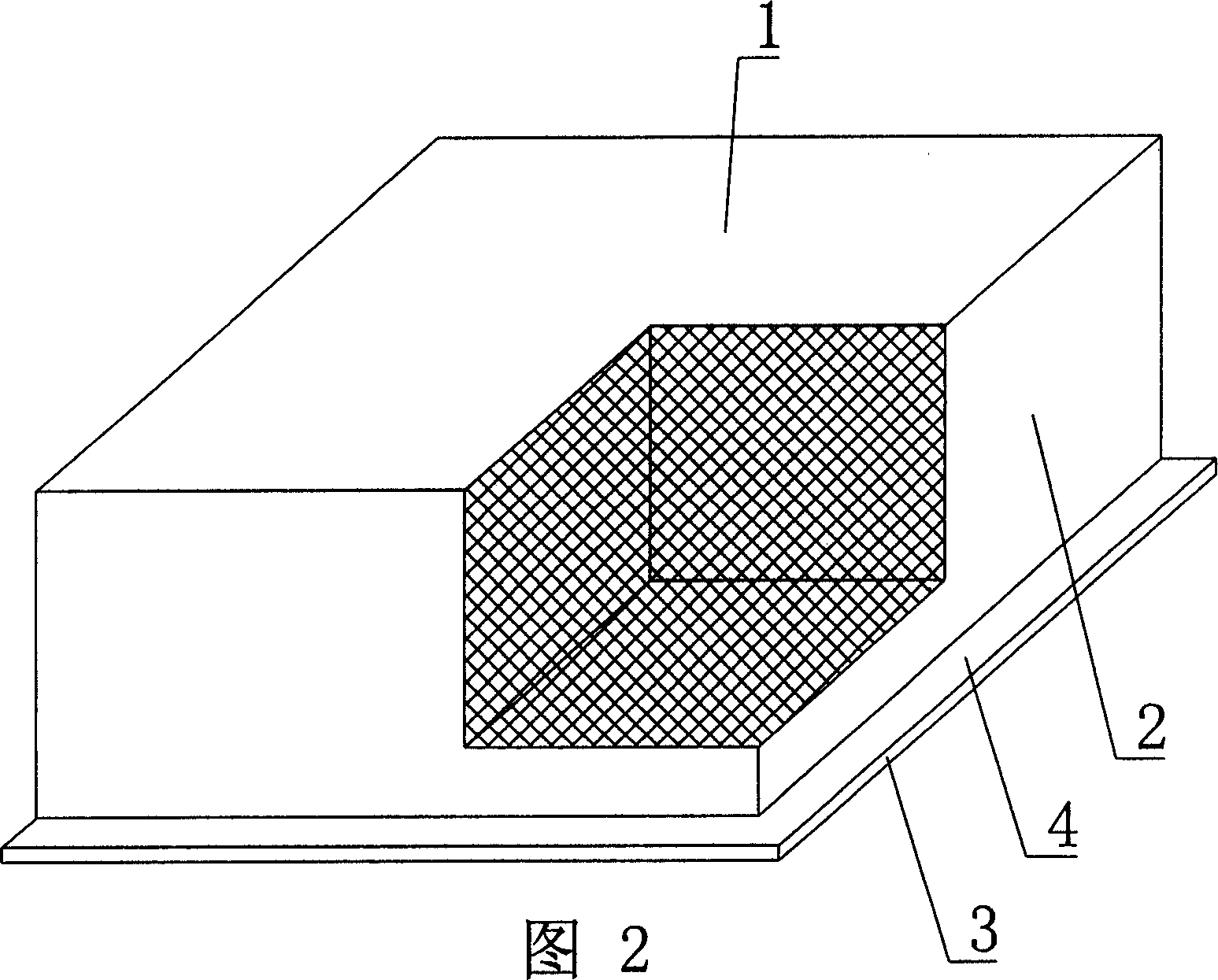
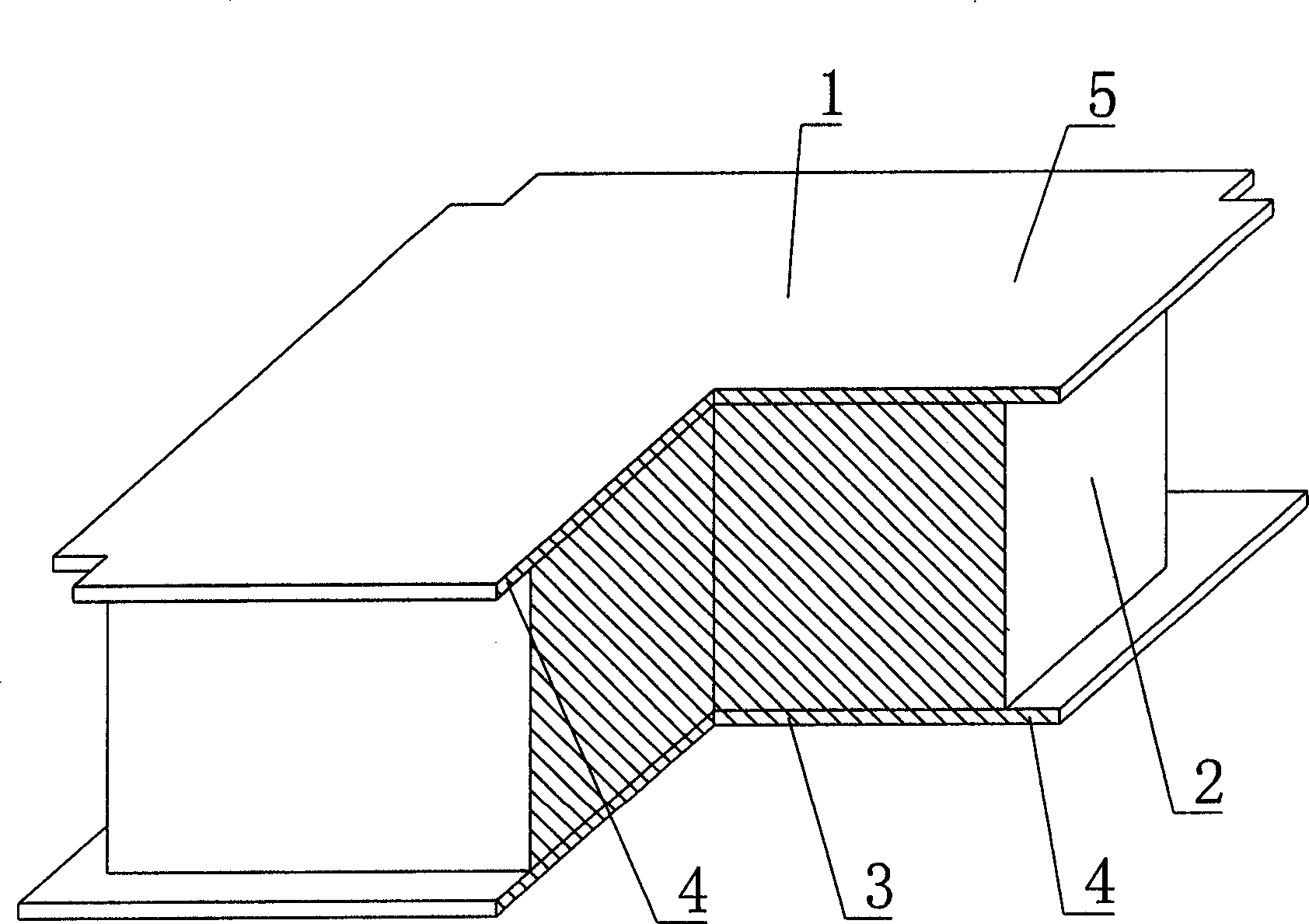
[0038] As shown in the accompanying drawings, the present invention includes a polyhedral solid lightweight material component 1, which is characterized in that on at least one peripheral side 2 of the polyhedral solid lightweight material component 1, a pick plate 4 protrudes outward along the bottom surface 3. figure 1 It is a structural schematic diagram of Embodiment 1 of the present invention. In the accompanying drawings, 1 is a polyhedron solid lightweight material member, 2 is the surrounding side, 3 is the bottom surface, and 4 is a pick plate. In the following drawings, those with the same number have the same description. Such as figure 1 As shown, the surrounding side 2 of the polyhedral solid lightweight material member 1 is provided with a pick plate 4 protruding outward along the bottom surface 3 .

[0039] The present invention is also...


PUM


Abstract

A die shell brace member for casting-in-place concrete includes a polyhedron solid lightmaterial brace member characterizing that at least one of its sides extends along its bottom to form a cantilever slab. Thus, after the member is used in casting-in-place concrete floors, the cantilever can play the rote of a form of cast-in-place concrete ribs between shell members since the side of the member extends along its bottom to form a cantilever, and construction forms can be omitted.

Description

(1) Technical field [0001] The invention relates to a formwork component for cast-in-place concrete. (2) Background technology [0002] At present, the cast-in-place concrete floor is a widely used floor structure. The lightweight permanent tire mold filled in it has various hollow tubes and boxes, and the boxes are hollow or solid. For example, the patent No. ZL99249798.1, which the applicant applied for on November 29, 1999, is a utility model patent named "fiber-reinforced thin-walled member for reinforced concrete filling", which discloses a thin-walled formwork member, including an upper plate, The surrounding side walls, the lower bottom, and the upper plate, the surrounding side walls and the lower bottom form a polyhedral cavity. Another example is that the application number applied by the applicant on November 23, 2001 is 01140106.0, the publication number is CN1356442, and the name is an application for a patent for invention of "a cavity structure formwork for c...

Claims


Application Information

Patent Timeline
Patent Type & Authority Applications(China)
IPC IPC(8): E04B5/36
Inventor 邱则有
Owner 湖南邱则有专利战略策划有限公司
Why Eureka
Try Eureka