Confocal raman cell

A confocal and lens technology, applied in instruments, optics, lenses, etc., can solve the problem of low Raman conversion efficiency, and achieve the effect of improving Raman conversion efficiency, compact structure, and high Raman conversion efficiency

Inactive Publication Date: 2005-02-16
SHANGHAI INST OF OPTICS & FINE MECHANICS CHINESE ACAD OF SCI
View PDF0 Cites 0 Cited by
  • Summary
  • Abstract
  • Description
  • Claims
  • Application Information

AI Technical Summary

Problems solved by technology

Therefore, the Raman conver

Method used


Image

  • Confocal raman cell

Examples


Embodiment Construction

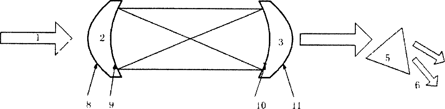
[0009] see now figure 1 , figure 1 It is a schematic structural diagram of an embodiment of the confocal Raman cell of the present invention. As can be seen from the figure, the confocal Raman cell of the present invention, the input window and the output window of the Raman cell are formed by the entrance lens 2 and the exit lens 3 directly installed at the two ends of the Raman cell. The lens 3 is a concave-convex lens composed of concave surfaces 9, 10 and convex surfaces 8, 11 with different radii of curvature. The concave surfaces 9, 10 form a confocal system relatively. The concave surface 10 of the exit lens 3 is coated with a dichroic film that is highly reflective to the pump light wavelength and anti-reflective to the Raman light wavelength.

[0010] The parallel incident pump light 1 is focused by the incident lens 2 and output 4 as parallel light at the exit lens 3, and then split by the prism 5 to obtain laser light with pump light wavelength 6 and Raman wavelen...


PUM


Abstract

The present invention relates to a confocal type Raman cell, and it is characterized by that the input window and output window of the Raman cell are formed from the incident lens and exit lens which are respectively and directly mounted on two ends of said Raman cell, the described incident lens and exit lens are concave-convex lens made up by uisng concave face and convex face with different curvature radiuses, its concave face is retatively formed into confocal system, and the concave face of the described incident lens is coated with two-color film which has high transmission coefficient for pumping light wavelength and total reflection coefficient for Raman light wavelength, and the concave face of the described exit lens is coated with two-color film which has high reflection coefficient for pumping light wavelength and anti-reflection power for Raman light wavelength.

Description

technical field [0001] The invention relates to a Raman cell for stimulated Raman scattering, and relates to a confocal Raman cell for improving Raman conversion efficiency. Background technique [0002] The Raman cell generally used for stimulated Raman scattering consists of two flat quartz glass windows, and a lens group is placed outside the window of the Raman cell to form a focusing and collimating confocal system. The plate used as the window of the Raman cell is generally not coated, or only coated with an anti-reflection coating for Raman light. The pump laser passes through the Raman cell one-way, so the Raman conversion is also one-way. Therefore, the Raman conversion efficiency is not high. Contents of the invention [0003] The purpose of the present invention is to overcome the shortcomings of the above-mentioned existing Raman cell, and provide a confocal Raman cell, which can improve Raman conversion efficiency and has a compact structure. [0004] The o...

Claims


Application Information

Patent Timeline
IPC IPC(8): G02B3/00G02F1/35
Inventor 楼祺洪叶震寰董景星魏运荣
Owner SHANGHAI INST OF OPTICS & FINE MECHANICS CHINESE ACAD OF SCI
Why Eureka
Try Eureka