
Stator for a turbomachine

A turbine and stator technology, applied in gas turbine devices, mechanical equipment, engine components, etc., can solve the problems of pressure chamber temperature increase, air leakage collection, increase efficiency loss of stator cooling system, etc., to reduce manufacturing cost, reduce load, The effect of increasing the service life

Inactive Publication Date: 2005-02-16
SN DETUDE & DE CONSTR DE MOTEURS DAVIATION S N E C M A
View PDF1 Cites 8 Cited by
  • Summary
  • Abstract
  • Description
  • Claims
  • Application Information

AI Technical Summary

Problems solved by technology

[0004] However these labyrinth seals are currently used to seal pressure chambers, as described in document FR2744761, but these labyrinth seals do not prevent the collection of air leaks through this chamber
In particular, internal labyrinth seals do not prevent part of the hot air outside the pressure chamber from entering into it
This consequently leads to an increase in the temperature of the pressure chamber and thus to an increase in the efficiency loss of the stator cooling system

Method used


Image

  • Stator for a turbomachine
  • Stator for a turbomachine
  • Stator for a turbomachine

Examples


Embodiment Construction

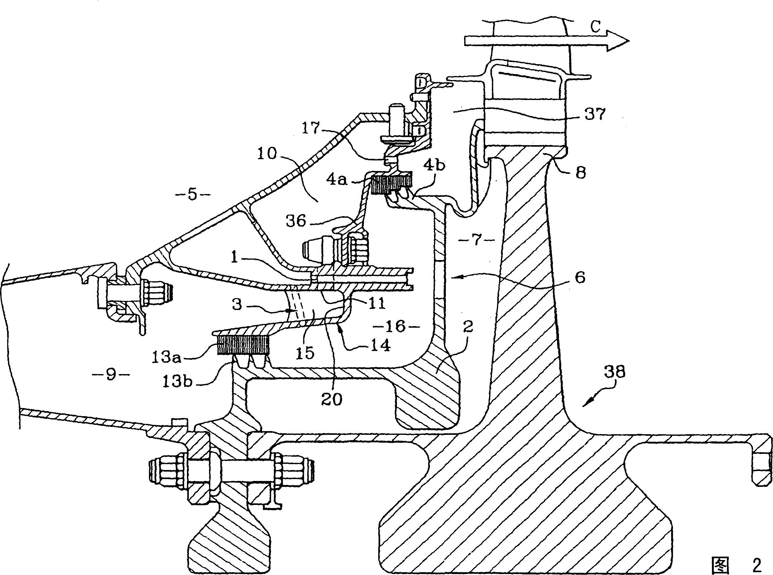
[0024] Referring to FIG. 2 , it can be seen that the turbojet engine notably comprises a stator according to the invention. The stator firstly comprises a pressure chamber 16 delimited by different elements. Note among these elements the outer labyrinth seals 4a, 4b, and the inner labyrinth seals 13a, 13b. The two inner and outer labyrinth seals 13 a , 13 b , 4 a , 4 b are respectively supported by a bracket 14 fixed to the cavity stator 5 and a further bracket 36 fixed to the bracket 14 . The inner labyrinth seal 13a, 13b partially defines a boundary between the pressure chamber 16 and the adjacent first cavity 9, while the outer labyrinth seal 4a, 4b partially defines a boundary between the pressure chamber 16 and the adjacent first cavity 9. The boundary between the adjacent second cavities 10 . The first and second cavities 9 and 10 are separated by a bracket 14 . Note that the stator, downstream of the second cavity 10 in the flow direction of the main duct of the turb...


PUM


Abstract

The stator, having a first injector (1) to deliver a main cooling air flow into a pressure chamber (16), a system (11) for evacuating air away from an internal labyrinth seal between a first cavity (9) and a second lower pressure cavity (10), and a second injector to remove air from the second cavity, has a third injector with at least one aperture (3) to create a forced air pressure adjacent to the labyrinth seal (13a, 13b) and with a high tangential component to the rotor (38). It also has at least one blade to create an air flow at a tangent to the turbine rotor.

Description

technical field [0001] The technical field of the invention is turbomachines, such as axial flow turbojet engines, comprising a stator for supplying air to other elements of the turbomachine. The stator is in particular a mechanical component that allows the supply of cooler air to the blades of the high pressure turbine, said air being drawn in the bottom of the combustion chamber, in particular for cooling a part of the rotor. Background technique [0002] In known embodiments of stators of existing turbomachines, it is generally seen: an element such as a main injector, which allows the acceleration of the air drawn in the cavity of the stator; side plates, which are able to guide the air to the blades of the high pressure turbine; and a different air circuit that allows the amount of air flow through the system to be corrected. These air flows are then injected into different cavities which then allow the heating of the defined mechanical components. According to these...

Claims


Application Information

Patent Timeline
Patent Type & Authority Applications(China)
IPC IPC(8): F01D11/04F01D1/00F01D5/08F01D11/00F01D11/02F01D25/00F02C7/28
CPCF05D2260/6022F01D5/081Y02T50/671Y02T50/673F05B2260/603Y02T50/676F01D11/001Y02T50/60F01D5/08
Inventor J·B·阿里拉A·加朗M·G·P·阿科J·-P·-J·马弗里
Owner SN DETUDE & DE CONSTR DE MOTEURS DAVIATION S N E C M A
Learn More