Plaster hollow large panel pouring concrete wall and manufacturing method thereof

A technology of pouring concrete and manufacturing method, which is applied to the on-site preparation of formwork/formwork/work frame, wall, building components, etc., can solve the requirements of environmental protection, economical rationality, good seismic performance cannot realize the industrialization of residential buildings And other issues

Active Publication Date: 2005-02-23
天津市房屋鉴定建筑设计院
View PDF0 Cites 5 Cited by
  • Summary
  • Abstract
  • Description
  • Claims
  • Application Information

AI Technical Summary

Problems solved by technology

Another example is that although the low-rise small-beam dense-column quick-installation house is different from the existing structural system, this structural syste

Method used


Image

  • Plaster hollow large panel pouring concrete wall and manufacturing method thereof
  • Plaster hollow large panel pouring concrete wall and manufacturing method thereof
  • Plaster hollow large panel pouring concrete wall and manufacturing method thereof

Examples


Embodiment 1

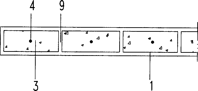
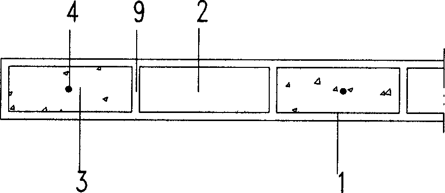
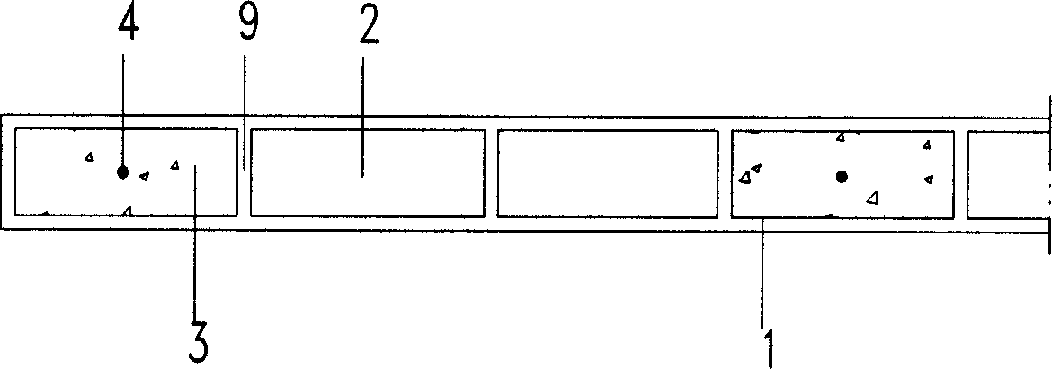
[0055] The porous gypsum hollow board (1) is relatively parallel and vertically arranged on the floor (7), the lower end of the porous gypsum hollow board (1) is connected with the upper end of the floor (7), and the upper end of the porous gypsum hollow board (1) is connected with the upper end of the porous gypsum hollow board (1). The lower ends of the floors (7) are connected.

[0056] The central part of the porous gypsum hollow plate (1) is provided with several plate ribs (9) relatively parallel and equidistant along the porous gypsum hollow plate (1) to form several hollow holes (2), and the hollow holes (2) of the porous gypsum hollow plate (1) ) is relatively parallel and perpendicular to the floor (7).

[0057] The central part of the hollow hole (2) of the porous gypsum hollow plate (1) is provided with several vertical steel bars (4) relatively parallel to the porous gypsum hollow plate (1), and concrete is poured into the hollow hole (2) of the porous gypsum holl...

Embodiment 2

[0059] One end of the porous gypsum hollow plate (1) is connected to the other end of another porous gypsum hollow plate (1) in a relatively vertical L shape, and the porous gypsum hollow plate (1) is connected to the other porous gypsum hollow plate (1). The cross-sectional area of ​​the connected hollow holes (2) forms an L-shape. Inside the L-shaped hollow hole (2), several vertical steel bars (4) are arranged relatively parallel to the porous gypsum hollow plate (1), and the porous gypsum hollow plate (1) is connected to the other In the L-shaped hollow hole (2) at the end connected by a porous gypsum hollow plate (1), several horizontal reinforcing bars (5) are arranged relatively parallel to the porous gypsum hollow plate (1), and the horizontal reinforcing bars (5) and the vertical reinforcing bars (4) are connected with each other, the end L-shaped hollow hole (2) where the porous gypsum hollow plate (1) is connected with another porous gypsum hollow plate (1) is poured...

Embodiment 3

[0063] In the middle part of the hollow holes (2) of the porous gypsum hollow plate (1) separated by at least one hole, several vertical steel bars (4) are arranged relatively parallel to the porous gypsum hollow plate (1), and the hollow holes of the porous gypsum hollow plate (1) (2) The inner pouring concrete constitutes the pouring core column (3), and the lower end and the upper end of the pouring core column (3) are respectively connected with the upper part of the floor (7) ring beam (8) and the upper part of the floor (7) ring beam (8). The lower part is connected.

[0064]In the hollow hole (2) adjacent to each end of the L-shaped hollow hole (2), several vertical steel bars (4) are arranged relatively parallel to the porous gypsum hollow plate (1), and each end of the L-shaped hollow hole (2) In the adjacent hollow holes (2), a number of horizontal steel bars (5) are arranged relatively parallel to the porous gypsum hollow plate (1), one end of the horizontal steel b...


PUM


Abstract

The present invention relates to a gypsum hollow plate concrete-poured wall body and its construction method. Said method includes the following steps: on a floor slab relatively vertically setting perforated gypsum hollow plate material; in the middle portion, along the perforated gypsum hollow plate material relatively-parallelly and equidistantly setting several ribs of plate so as to form several hollow holes in the middle portion of the hollow hole relatively-parallelly setting several vertical steel bars, pouring concrete into hollow hole to form poured core column, the lower end portion and upper end portion of the poured core column are respectively connected with the upper portion of floor slab ring beam and lower portion of floor slab ring beam so as to obtain the whole body building. Said invention adopts the environment-protecting type material as form, and can shorten construction period.

Description

technical field [0001] The invention relates to a wall body used for buildings, in particular to a gypsum hollow slab poured concrete wall body and a manufacturing method thereof. Background technique [0002] At present, the country's policy on the use of solid clay bricks in buildings is to restrict and eliminate the use of solid clay bricks. In the construction market, various structural systems continue to emerge. Using various new materials and new structures to apply to buildings has its own obvious disadvantages, such as the high cost of steel structure houses, short-leg shear walls, and special-shaped columns. Structural construction is difficult to guarantee, hollow block construction is difficult, etc. These situations more or less affect the development of residential buildings in the direction of industrialization. Another example is that although the low-rise slab-type fast-installed houses with small beams and dense columns are different from the existing stru...

Claims


Application Information

Patent Timeline
IPC IPC(8): E04B2/86E04C5/01E04G11/06
Inventor 邓永胜任达姜黎明霍俊青洪弦哲张健强吕强苑志刚唐俐
Owner 天津市房屋鉴定建筑设计院
Why Eureka
Try Eureka