Roofbolt constructing method in civil engineering

A technology of anchor bolt construction and civil engineering, applied in the direction of structural elements, building components, building reinforcements, etc., can solve the problems of low pullout resistance of anchor bolts, difficulty in lowering anchor bars, etc., and meet the needs of foundation pit support and construction procedures The effect of reducing and enlarging the diameter

Inactive Publication Date: 2005-02-23
GUANGDONG JINHUIHUA GROUP
View PDF0 Cites 14 Cited by
  • Summary
  • Abstract
  • Description
  • Claims
  • Application Information

AI Technical Summary

Problems solved by technology

This method can effectively solve the problem of difficulty in lowering the anchor bar during the construction of the anchor rod in the sand layer and the problem of small pull-out resistance of the anchor rod in the soft soil layer

Method used


Image

  • Roofbolt constructing method in civil engineering
  • Roofbolt constructing method in civil engineering
  • Roofbolt constructing method in civil engineering

Examples


Embodiment 1

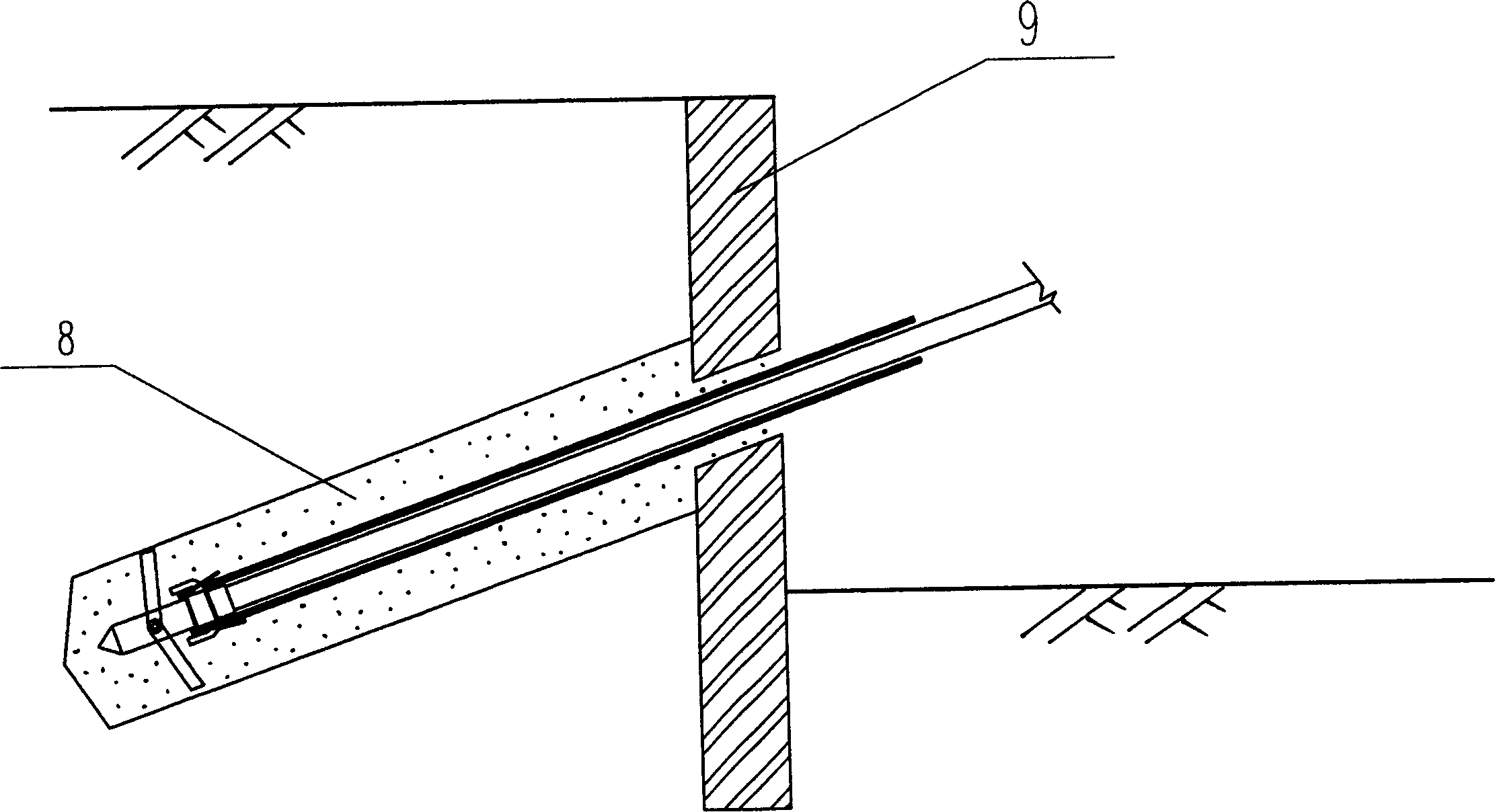
[0022] First, open a Φ120 hole on the support pile 9 of the foundation pit, and connect the movable hook 2 to the rear end of the drill bit 1. The movable hook 2 can rotate freely relative to the drill bit 1, but cannot move freely, that is, the movable hook 2 It needs to move back and forth with the drill bit 1; hinge the drill piece 4 on the drill bit 1, and the drill piece 4 is located at the front end of the movable hook 2; disassemble and fold back the steel wires 6 at the front ends of the two 7Φ5 steel hinge lines 5, and put the steel wires together. The line 6 is buckled on the movable hook 2, that is, when the movable hook 2 moves forward, the anchor rib 5 is moved forward, and when the movable hook 2 moves backward, the anchor rib 5 can be separated from the movable hook 2 , fix the drill pipe 3 and the drill bit 1 with threaded connection, see the connection relationship of each part figure 1 Shown; close up the drill piece 4 on the drill bit 1, pass the drill bit 1...

Embodiment 2

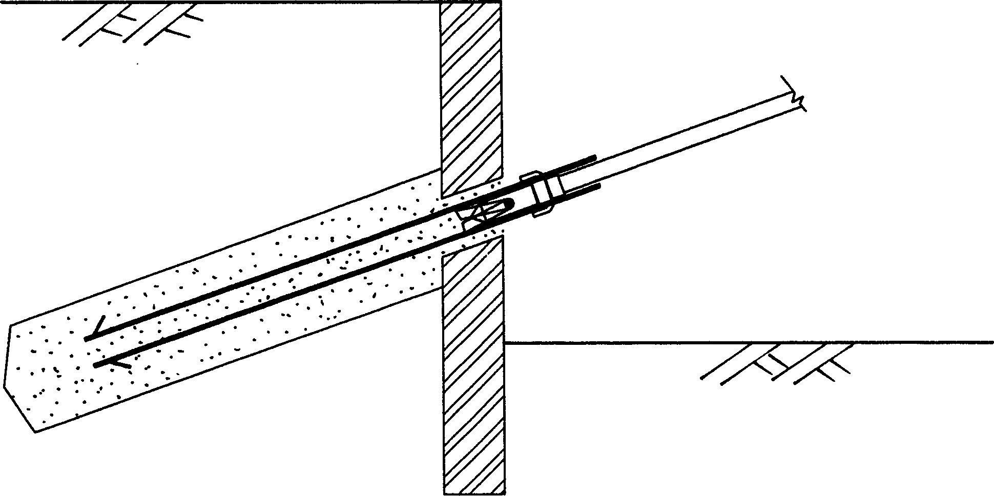
[0024] In Embodiment 1, the steel hinge wire 5 is replaced with Φ25 steel bars 10, two reflexed steel bars 11 are welded at the front ends of the steel bars 10, the reflexed steel bars 11 are buckled on the movable hook 2, and the extension of the movable hook 2 The arm is set to be foldable, that is, the arm stretches out when drilling forward, and retracts when moving backward, so as to reduce the resistance when the drilling rod 1 etc. is pulled out. The connection of other parts is the same as that in the first embodiment; start the drilling rig, use mud circulation fluid, rotate the drill bit 1 to drill forward and drive the Φ25 steel bar 10 to follow up through the movable hook 2, and after drilling to the predetermined depth, clean the hole, and then pour cement at the same time The 8 sides of the slurry continue to drill forward, such as Figure 4 As shown: After reaching the designed length of the anchor rod, pull out the drill pipe 3, drill bit 1, drill piece 4 and m...


PUM


Abstract

The present invention discloses an anchor rod construction method used in the civil engineering field. The described anchor rod construction is characterized by that the drill rod and drill bit are fixedly connected together, a movable hook is cover-mounted on the drill rod or drill bit, the movable hook and anchor bar are connected by adopting clasp joint mode. When the drill bit is forwards drilled, the anchar bar also can be driven and also forward advanced, then the solidifying materials of cement slurry, etc. are injected into the hole by means of drill rod, and after the solidifying materials are reached to predefined hole depth, the components, of drill rod and drill bit can be drawn out, the remained anchor bar and solidifying materials can be formed into anchor rod together.

Description

technical field [0001] The invention relates to a bolt construction method in civil engineering. Background technique [0002] In the existing common anchor rod construction technology: first use drilling rig drilling or Luoyang shovel to form a hole, then clear the hole, lower the anchor bar, pour cement mortar or pure cement slurry to form the anchor rod. This is the construction method of most anchor bolts at present, and the method is mature and simple. However, for sand layers with good water-rich properties, this construction method is difficult to implement. The main reason is that it is difficult to form holes, and the sand layers are easy to collapse holes, so that the anchor bars cannot be lowered. In addition, in the soft soil area, due to the low frictional resistance of the soft soil, the anchor rod needs to be designed longer to have a certain pullout resistance. The soft soil layer is prone to shrinkage and it is very difficult to lower the anchor bar. All o...

Claims


Application Information

Patent Timeline
Patent Type & Authority Applications(China)
IPC IPC(8): E04C5/12
Inventor 陆观宏
Owner GUANGDONG JINHUIHUA GROUP
Why Eureka
Try Eureka