
Detection and correction for distancing light and detector relative position

A technology of relative position and detection method, applied in the direction of measuring device, testing the alignment of automobile headlights, instruments, etc., can solve the problem of not detecting the angle error of headlights, affecting the detection accuracy of light intensity, light intensity and irradiation position error big problem

Inactive Publication Date: 2005-02-23
吴明
View PDF0 Cites 11 Cited by
  • Summary
  • Abstract
  • Description
  • Claims
  • Application Information

AI Technical Summary

Problems solved by technology

Since the intensity of the headlight light is converted by detecting the illuminance, the calculated light intensity is proportional to the square of the distance from the light source after the illuminance is detected. Will seriously affect the detection accuracy of light intensity
The angle limit of the headlight irradiation position is very small. The position error between the headlight and the detector caused by the random parking position of the vehicle directly affects the horizontal deflection distance of the headlight. At present, the headlight detection does not detect the high beam The distance between the light source and the light metering screen, and the angle error of the headlight relative to the detector are not detected. The detected light intensity and irradiation position have large errors, and the repeatability is extremely poor.

Method used


Image

  • Detection and correction for distancing light and detector relative position
  • Detection and correction for distancing light and detector relative position
  • Detection and correction for distancing light and detector relative position

Examples


Embodiment Construction

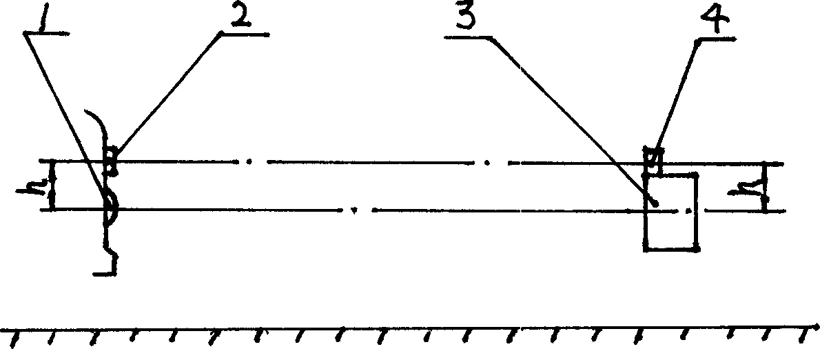
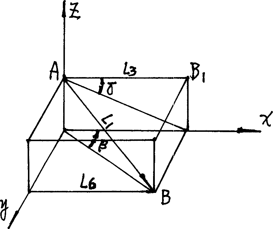
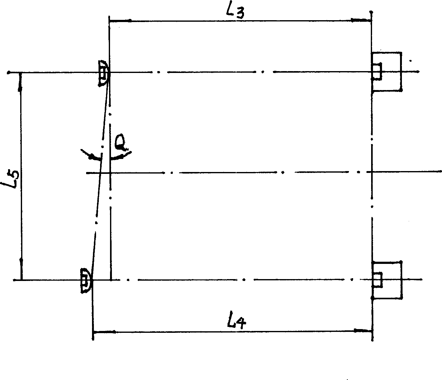
[0042] Usually the headlights are detected from left to right. The four-lamp system stipulates that they should be installed side by side. The pair installed on the outside is a high and low beam double beam lamp, and the pair installed on the inside is a high beam single beam lamp. In order to increase L 5 To improve the detection accuracy, it is best to place the ranging sensor or signal reflector at the corresponding position above the center of the double beam lamp. For passenger cars, it is usually adsorbed on the high beam from top to bottom. For trucks, Usually the cantilever is attached to the high beam. The absolute error of ranging has little effect on the detection error of light intensity. The error of 10mm relative to the distance error of 1000mm is only 1%, but the relative error of ranging on both sides has a great influence on the angle error. Therefore, as long as the ranging sensor or signal reflection The body is in the relative symmetrical position on the ...


PUM


Abstract

A method for measuring relative position of distance light to detector includes using cetre connection line of light in parallel to track of detector as centring position of the light and detector, moving up and down as well as left and right in certain distance for contring light source centre to light test screen centre, measuring equal height h and vertical distance, L3 and l4 of the two to obtain centre distance l5 and error angle Q, using these figure to revise detection value.

Description

technical field [0001] The invention improves the detection accuracy of the headlight by accurately detecting the relative position between the high beam lamp and the detector when detecting the headlight of the automobile, and belongs to the technical field of automobile detection. Background technique [0002] Car headlights are divided into high beam and low beam. The high beam has the requirements of light intensity and irradiation position, and the low beam also has the requirement of irradiation position, which is an important condition to ensure the safe driving of the car at night. Since the intensity of the headlight light is converted by detecting the illuminance, the calculated light intensity is proportional to the square of the distance from the light source after the illuminance is detected. It will seriously affect the detection accuracy of light intensity. The angle limit of the headlight irradiation position is very small. The posi...

Claims


Application Information

Patent Timeline
IPC IPC(8): G01M11/06G01M17/00
Inventor 吴明
Owner 吴明
Learn More